
Obstacle Avoidance
Obstacle avoidance is one of the most important aspects of mobile robotics. Without it robot movement would be very restrictive and fragile. This tutorial explains several ways to accomplish the task of obstacle avoidance within the home environment. Given your own robots you can experiment with the provided techniques to see which one works best.There are many techniques that can be used for obstacle avoidance. The best technique for you will depend on your specific environment and what equipment you have available. We will first start with simpler techniques that are easy to get running and can be experimented on to improve their quality based on your environment.
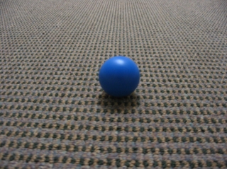
Let's get started by first looking at an indoor scene that a mobile robot may encounter.
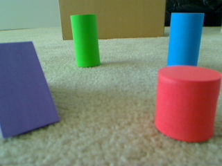
Here the robot is placed on the carpet and faced with a couple obstacles. The following algorithms will refer to aspects of this images and exploit attributes that are common in obstacle avoidance scenarios. For example, the ground plane assumption states that the robot is placed on a relatively flat ground (i.e. no offroading for these robots!) and that the camera is placed looking relatively straight ahead or slightly down (but not up towards the ceiling).
By looking at this image we can see that the carpet is more or less a single color with the obstacles being different in many ways than the ground plane (or carpet).
Edge Based Technique
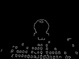
The first technique that exploits these differences uses an edge detector like Canny to produce an edge only version of the previous image. Using this module we get an image that looks like:
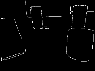
You can see that the obstacles are somewhat outlined by the edge detection routine. This helps to identify the objects but still does not give us a correct bearing on what direction to go in order to avoid the obstacles.
The next step is to understand which obstacles would be hit first if the robot moved forward. To start this process we use the Side_Fill module to fill in the empty space at the bottom of the image as long as an edge is not encountered. This works by starting at the bottom of the image and proceeding vertically pixel by pixel filling each empty black pixel until a non-black pixel is seen. The filling then stops that vertical column and proceeds with the next.
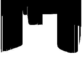
You will quickly notice the single width vertical lines that appear in the image. These are caused by holes where the edge detection routine failed. As they specify potential paths that are too thin for most any robot we want to remove them as possible candidates for available robot paths. We do this by using the Erode module and just eroding or shrinking the current image horizontally by an amount large enough such that the resulting white areas would be large enough for the robot to pass without hitting any obstacle. We chose a horizontal value of 20.

Now that we have all potential paths we smooth the entire structure to ensure that any point picked as the goal direction is in the middle of a potential path. This is based on the assumption that it is easier to understand the highest part or peak of a mountain as compared to a flat plateau. Using the Smooth Hull module we can round out flat plateaus to give us better peaks.
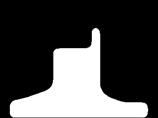
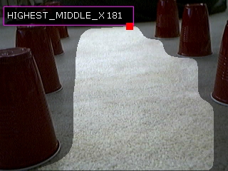
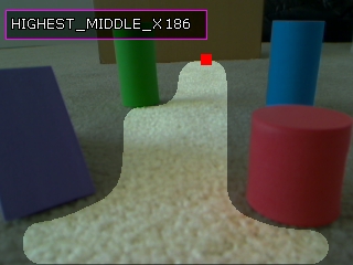
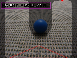
Once this is done we now need to identify the highest point in this structure which represents the most distant goal that the robot could head towards without hitting an obstacle. Based on the X location of this point with respect to the center of the screen you would then decide if your robot should move left, straight, or right to reach that goal point. To identify that location we use the Point Location module and request the Highest point which is identified by a red square.
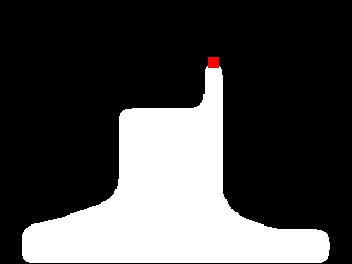
Finally just for viewing purposes we merge the current point back into the original image to help us gauge if that location appears to be a reasonable result.
Given this point's X location at 193 and the middle of the image at 160 (the camera is set to 320x240) we will probably move the robot straight. If the X value were > 220 or < 100 we would probably steer the robot to the right or left instead.
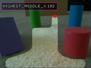
Some other results using this technique.
This works reasonable well as long as the floor is a single color. But this is not the only way to recognize the floor plane ...
Blob Based Technique
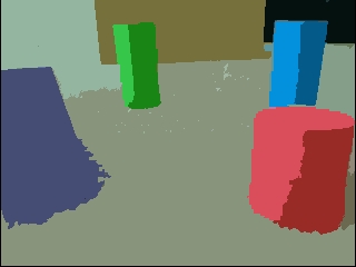
The second technique exploits the fact that the floor is a single large object. Thus starting with the original image we can segment the image into a smaller number of colors in order to connect pixels into blobs that we can process. This grouping can use either the Flood Fill module or the Segment Colors module. Using the flood fill module the image becomes
The next step is to isolate the largest blob in the image which is assumed to be the floor. This is done using the Blob Size module which is set to just return the single largest blob in the image.
We then dilate this image by 2 pixels using the Dliate to close all the small holes in the floor blob.
Then we negate this image and use the same Side Fill module as before to determine the possible vertical routes the robot could take. We need to negate the image prior to this module as the Side_Fill module only fills black pixels. In the above image the object to be filled is white and thus when negated will become black.
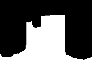
From here on the stages are the same as the previous technique. Namely Erode to remove small pathways, smooth the resulting object and identify the top most point. The final image looks similar to the previous technique.
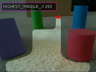
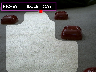
The results are very similar but the first technique exploited edges whereas this one exploited connected pixels of similar color. But the issue of the similar colored floor plane still remains. What happens if you do not have the same colored carpet? For example, suppose that you have a high frequency pattern in a carpet.
The resulting edge and blob based techniques will not work as the blob and edge detection will pick up on the small patterns of the carpet and incorrectly see them as obstacles.
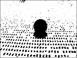
You can notice the failure of both these techniques in the above images which if fully processed would only see non-obstacle space in the lower 10 pixels of the image. This is clearly incorrect!
Floor Finder Technique
To improve on our last image we will need to understand that the carpet or floor plane contains more than one pixel color. While you could detect both colors and perhaps merge them in some way an easier approach is to make an assumption that the immediate foreground of the robot is obstacle free. If we were to sample the colors in the lowest part of the image which is the immediate space in front of the robot we could use these color samples and find them in the rest of the image. By searching for all pixels who share the same or similar color to those pixels in this sample space we can theorize that those pixels are also part of the floor plane.This process can be accomplished using the Floor Finder module. Given our test image
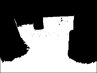
we can run the floor finder module to procedure a theoretical mask of what the floor might be.
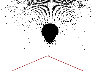
We can see the red triangle that represents the sample area that is used to understand what pixel colors are likely to be floor pixels. The white pixels in the above image now represent all pixels in the image that are similar to those found in the triangle. We can see that this works quite nicely to segment out the floor plane. We then dilate the image to remove small holes in the floor plane.
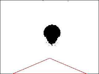
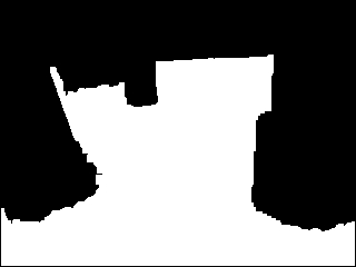
Then we negate this image and use the same Side Fill module as before to determine the possible vertical routes the robot could take. We need to negate the image prior to this module as the Side_Fill module fills black pixels. In the above image the object to be filled is white and thus negated it will become black.
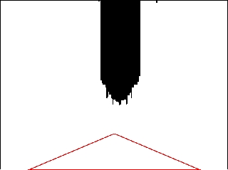
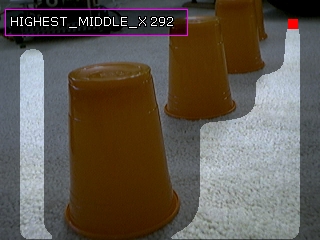
Following a similar sequence as before we Erode to remove small pathways, smooth the resulting object and identify the top most point. The final image is used to verify the recommended goal point.
We then run the same technique over the previous image to check if that still works.
Which it apparently does! So the floor finder module has allowed us to use a single technique for both similar colored carpet to one that has a lot of small internal patterns in it.
Obstacle Avoidance
Notes:
1. Three techniques were discussed with the final technique being the most stable given the test images we used. Your experience will be different. It is worth testing each technique on your own images to get a sense of how stable they are and which one will work best for you.
2. Keep in mind when moving the code into a robotic control that the horizontal erode is used as a gauge to the robot's width. You will have to experiment with your setup to determine which erosion width is best for your robot.
3. The final variable displayed has the X value of the goal point. That X value should be then used by your application or within the VBScript module to create a value that will control your servos. It could be as simple as
midx = GetVariable("IMAGE_WIDTH") / 2
leftThreshold = midx - 50
rightThreshold = midx + 50
if x <= leftThreshold then
SetVariable "left_motor", 0
SetVariable "right_motor", 255
else
if x >= rightThreshold then
SetVariable "left_motor", 255
SetVariable "right_motor", 0
else
SetVariable "left_motor", 255
SetVariable "right_motor", 255
end if
end if
Your turn ...
Want to try this yourself? Following is the robofile that should launch RoboRealm with the original image we used in this tutorial. You can click on each of the steps in the pipeline to review what the processing looks like up to that point.
![]() Download Floor Finder robofile
Download Floor Finder robofile
The End
That's all folks. We hope you've enjoyed this little adventure into an application of machine vision processing. If you have any questions or comments about this tutorial please feel free to contact us.
Have a nice day!
| New Post |
| Obstacle Avoidance Related Forum Posts | Last post | Posts | Views |
|
How can I make my car autonomous
I want to make my own platform with servos (Parallax servo controller) I want to know Step by step how to do this, The car will... |
14 year | 1 | 4867 |