
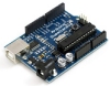
Sparkfun Arduino Uno/Mega
The Sparkfun Arduino modules provides an interface to the Arduino Duemilanove or the Mega sold by Sparkfun. These boards have a USB to serial connection with a PC and can operate at 115200 baud which makes it an ideal platform for communication with a PC. The Duemilanove has 6 PWM (Servo) capable digital signals, 6 10bit analog in and 14 digital IO lines (shared with the 6 used for PWM). The Mega has 14 PWM (Servo), 16 Analog and 32 Digital IO lines. Thus, you can use these inexpensive boards as a servo controller and an analog/digital IO board for your robotic projects.These modules are meant to allow RoboRealm to communicate with an Arduino while connected via USB or bluetooth wireless link. It requires you to download the Uno Sketch or Mega Sketch (Arduino programs) into the Arduino board in order to facilitate communication with this module in RoboRealm.
From there you can use the Arduino as a servo controller, digital IO, input device, etc. from within RoboRealm by setting or reading the variables set by this module. If you have special requirements you can also modify the Sketch program to do other processing (the link above is to the source code).
Naturally, you can roll your own RoboRealm Arduino communication using the Serial module but having a stock module perform this means you can test things out quickly without needed to understand the internal programming of the Arduino.
The communication protocol that the module uses to communicate with the Arduino is a simplistic 1 or 4 byte packet. The data transmitted is a 7 bit value with the 8th bit being a sync bit in case the Arduino and PC become out of alignment. Only the header bit has the 8th bit set, all other bytes do not. This allows that when a new packet is to be processed that the first and only first byte has bit 8 set.
For the Uno/Due the 6 PWM lines are part of the 14 digital IO lines. If you need to control 6 servos then you will have 6 less digital IO lines. Pins 0 and 1 are tied to the serial communication and therefore when communicating over serial to a PC are not available for general use.
For the commands that do not require a value payload they only require 1 byte. This byte includes the 128 sync bit, the command 0-7, and the channel 0-6 or 2-14. The 4 packet size is used for those commands that have a value payload such as setting a servo position (typically 500-2500) which requires 2 bytes for the data. The 3rd byte used is a CRC to ensure that they header and values were all received together and have not been mixed up.
Values such as the analog signals are also passed back to the PC using the same 4 byte structure also including a CRC to be sure that the bytes where received in order correctly.
Interface

Instructions
1. Setup - Open the Arduino development environment and download this Sketch and upload it to your Arduino. The provided Sketch is how the communication between the PC and the Arduino is accomplished. Note that this is NOT a new bootloader program but just a regular user Sketch running on the Arduino. It is required otherwise the PC will not be able to tell the Arduino what settings to make nor be able to read any analog or digital values.
The Sketch can be modified as per your needs but you will need to be careful not to destroy any of the functionality otherwise the RoboRealm module may stop working as expected if it is not getting the right signals back from the Arduino.
2. Com Port - Specify the COM port that your Arduino is connected to. Note that the Duemilanove comes with a USB cable that simulates a serial port on your PC. The port number for these kinds of virtual ports are normally above the standard 1-4 physical ports.
3. Baud Rate - Specify the baud rate of 115200 to communicate with the Arduino. Note that this is much higher than the standard 9600 normally used. The higher rate provides much better responsiveness than the lower rates.
4. Remember As Default - Select the "Remember as Default" checkbox if you would like the current COM setting to be remembered by RoboRealm such that whenever the Arduino module is loaded the COM port and buad rate will be auto-populated to the current setting. This ability allows you to not have to constantly change the COM port setting when loading in successive RoboRealm robofile configurations.
5. Servos - Once communications are specified and you have a servo hooked up to the board you should be able to move the appropriate slider according to which pin you used in order to see the servo move. Note that the Duemilanove does NOT come with standard 3 pin servo connectors so you will need to connect the red/orange to power, black/brown to ground, and white/yellow to the pin you'd like to use. If the servo does not move, check your wiring off the servo, check that you have an external power supply connected (some servos are very power hungry) and check that the COM port/USB cable are all connected and properly specified. Note that you will be using the same port as the Arduino environment uses to upload applications so be sure that you are done uploading the Sketch before testing. Since RoboRealm holds the COM port open you will need to exit RoboRealm in order to upload a new Sketch.
6. Variables - Select the appropriate variables that contain or will contain the position value that will be sent to the servo board. This is used to automatically change the servo values based on your VBScript (using the SetVariable function) or Plugin based program.
7. Current Value - To manually set the servo position type in the appropriate number (500-2500, 1500 is the default neutral) into the text area or use the slider to adjust the value. The servo position will be updated as appropriate. Note that the current limits of 500 and 2500 will most likely be beyond the capabilities of your servos so you may want to tighten the range.
8. Sliders - You should be able to move your servos by dragging the sliders to the right or left or by specifying a number within the current value text box. If the servos do not move check your USB cable and/or board power connections.
9. Min/Max Limits - You can also use the min/max limits to ensure that even if the variables specify large or low values (due to programming errors) that the board does not actually attempt to move the servos above or below the specified limits. This can be used as an additional precaution in case your servos cannot physically move beyond certain limits.
10. Analog Input - If you want to sample the analog values specify a variable or type one in that will contain the value from the appropriate pin. Note that you must select the checkbox next to the Analog Pin in order to activate this functionality. As soon as the pin is activated the value read at that pin will be displayed. Note that even when unattached the pin will show a very low <200 value due to noise. Also note that when pin 0 goes high that other ungrounded pins will also go high due to signal bleed.
Once the value is placed within the variable you can then use this value in other modules, or accessed via the API, extension, etc. in order to move the value outside of the RoboRealm application.
11. Analog Output - If you want to send a specific voltage out over the analog pins specify a variable or type one in that will contain the value or type in a number from 0 to 255 in the provided text box. This will cause the Arduino to send a frequency wave over that pin which averages to a specific voltage, Note that while this is a form of PWM is it not the same format as that used to control servos.
Note that the analog out pins are NOT the same as the analog input pins but are in fact the same pins used in controlling servos and digital pins 3,5,6,9,10 and 11. These pins are functionally shared between servos, analog out and digital pins so use them sparingly!
12. Digital Pins - The Arduino comes with 14 digital IO pins that can be configured as an input or an output. Unlike Analog pins, Digital pins can only receive a 1 or 0 (on or off) as apposed to a full numeric value. Likewise, a digital pin set to an output can only send an on or off to the pin similar to a switch.
The module provides a way to either receive or send signals to these pins via the RoboRealm_Arduino Sketch program. Note that several of the pins are used by the Servos and thus enabling them as a digital pin will DISABLE the appropriate Servo to indicate this pins reassignment.
Each pin can either be set as an input or output. Do this by selecting the "in" or "out" radio button next to each pin. If you are specifying a pin as an output selecting the checkbox will then turn that pin high or low. Be sure the enable the pin (first checkbox) to enable the controls for that pin. Again, if you enable pin 3,5,6,9,10,11 a Servo configuration in the first tab will be disabled. These pins are marked with a '*' in the Digital tab.
For input pins the checkbox will reflect the read high or low state of the pin but will remain disabled.
To automatically send or receive a bit select or type in a variable that will be set if the pin is configured as an input or read into if the pin is configured as an input. Note that you can tell RoboRealm which bit of the variable you want to set/get by using the provided bit dropdown.
As an experiment, you can connect an LED to pin 2 and then select the pin as an "out", By checking and un-checking the checkbox you can make the LED blink. Alternatively, if you don't have an LED handy try this on pin 13 as that is connected to the LED next to the Tx and Rx leds on the Duemilanove.
If you then select the IMAGE_COUNT variable (which holds the current image counter) as the variable and select Bit 0 the LED will blink for every two frames captured. Selecting successively higher bits will slow the blinking by a factor of 2 for every bit.
See Also
Axon
Parallax BoeBot
A-WIT BOL-BOT
For more information
Arduino
Sparkfun Arduino Duemilanove
| New Post |
| Sparkfun_Arduino Related Forum Posts | Last post | Posts | Views |
|
Hi, good days. im unable to perform serial communication to arduino. i attach robo file and arduino source code for your referen... |
9 year | 5 | 4778 |
|
Roborealm and Sparkfun_Arduino Module
Hello Steven, We use Roborealm for object recognition. And we send booleans (if the object is ok or nok) to arduin... |
9 year | 3 | 3166 |
 If a Different Object Recognized= Different Robot Action
Hello, I have three different objects. The Object Recognition module performs excellent and if any of the three ob... |
9 year | 4 | 3711 |

Hi. I am new to RR and so putting my query with great hope. My project is to detect the internal defects in an egg. This can be ... |
9 year | 2 | 3246 |
|
Hello, I've been following the tutorial for automatic gun turret. It have 2 servos for pan and tilt... |
10 year | 3 | 3295 |
|
Hello all, I am participating in an underwater Robotics in competition. I am using roborealm for the entire contr... |
10 year | 11 | 4211 |
|
Arduino Uno R3 - Sparkfun
Hello, I am starting experimenting with Arduino Uno R3 and the Sparkfun Arduino interface. | 10 year | 3 | 3375 |
|
Read Inputs using Arduino Mega Module
I was under the impression that if you want to read the state of a digital pin (for example Pin 51) using the Arduino Mega modul... |
11 year | 2 | 3366 |
|
roborealm and arduino
I have connected my arduino mega with roborealm and it suppose to control servo but it received information from roborealm but m... |
11 year | 2 | 3636 |
|
avm navigator and arduino UNO
HI I want to use the navigator module with arduino UNO, and control the robot motors through arduino!! is it poss... |
11 year | 2 | 3525 |
|
Motors run after I close RR
Hi, I am working on object tracking. All i am doing is when the object is detected, the motors for goin... |
11 year | 2 | 3187 |
|
Servo control with arduino Uno through roborealm
Hello I am trying to control a servo with roborealm though the use of an arduino uno controller. I ... |
11 year | 2 | 3686 |
|
Differential Module to Servos
Hi!! Is it possible to use the differential drive module and get PWM outputs through Arduino module!! | 11 year | 2 | 3262 |
|
Communication
Hi Again- Ok, My application is steering towards using RR to output to an arduino, and use the arduino to run servo (or steppers... |
11 year | 2 | 3578 |
|
Boe Bot Arduino Shield module
Hi Folks, I recently purchased the roborealm software which is great. Unfortunately my main robot test ... |
11 year | 3 | 3663 |
|
Arduino Controling Roborealm via serial. (not the other way around)
Hello. I would like to know if there´s a way of switching between different roborealm behaviours v... |
12 year | 3 | 3838 |
|
Sparkfun-Arduino servo control not working
Hi I just downloaded roborealm and am having trouble interfacing to an arduino board. I simply want... |
12 year | 4 | 4687 |
|
I used the following code: RGB_Filter Green Center of Gravity Set x=[COG_X], y=[COG_Y]... |
12 year | 2 | 3761 |