
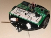
A-WIT BOL-BOT
The A-WIT BOL-BOT module provides access to the BOL-BOT robot made by A-WIT Technologies that runs the c-stamp microprocessor.The module expects to interact with a preloaded cstamp application that can be downloaded here or you can download the entire source for the project here.
The cstamp application expects to interact with a PC connected via bluetooth which needs to be assembled on the provided BOL-BOT breadboard. See the BOL-BOT website documentation for further instructions about connecting the BOL-BOT to a PC via bluetooth. Note that pins 36 (TXD), 34 (CTS), 35 (RXD), 33 (RTS) and 32 (RST) are assumed by the cstamp program as those in use by the ESD200 bluetooth chip.
Interface
Instructions
1. COM Port - First select the appropriate COM port where the bluetooth has been attached to. Note that only the COM ports that are recognized by the system are displayed. If you have not yet attached your bluetooth USB device or activated the internal bluetooth wireless capabilities you should do so before running RoboRealm otherwise the appropriate COM port will not show up.
Once RoboRealm has connected to the BOL-BOT successfully the LED4 will flash for as long as the connection is held. If either the PC or the BOL-BOT stops responding a 3 second failsafe will be activated and terminate the current BOL-BOT actions. At that time all servos will stop but pins will retain their last setting as specified by this module. If you want to use LED4 for your own purposes select the "Deactivate LED4 connection flashing".
2. Baud Rate - Select the appropriate baud rate. Currently the ESD200 supports 9600 baud so the default should be left as set.
3. Servos - To test the module ensure that two servos are connected to the servo pins 16-19 and slowly move the appropriate servo sliders. If everything is working the servos should slowly start to move. If this does not happen check the wiring on the bluetooth chip, check your COM port settings, or that your bluetooth device is on. Note that when first connecting the devices can take up to 30 seconds to secure a connection so be patient. Be on the lookup for the pairing password prompt that may pop up during the initial communication between your PC and the BOL-BOT. If you have not set a pairing password the default 1234 should suffice.
If the servos move you can then select a variable (or type one in) that will be populated from another module that will contain the values to send to the BOL-BOT. Note that 550 is considered neutral whilst 300 and 800 are the opposite extremes. If your servos move even when using 550 as a setting adjust the trim values until they stop. By customizing the trim values you could change servos without needing to adjust all the servo speeds used to calculate movements.
4. Bumpers - assuming you have constructed the bumpers on the BOL-BOT breadboard pressing one or both of the bumpers will change the appropriate checkbox by turning it on or off. Be sure to have enabled the Bumpers by clicking on the checkbox in the Bumpers tab which tells RoboRealm to start querying the bumper states on the BOL-BOT. Be sure to specify which pin the bumpers are connected to. If you are following the instructions in the BOL-BOT assembly you will have used pins 14 and 37.
If you want to access the bumper state from other modules select or type in the variable name that will contain a "1" when the bumper is pressed and "0" when the path is clear.
5. Photo Resistors - select the appropriate pin that a photo resistor is connected to and you should start seeing the bar graph adjust based on the detected lighting. Note that the value will range from 0 to 5 to reflect the amount of voltage (5V max) allowed to pass through the photo resistor. To utilize this number in other modules select or type a variable that will be set to the resistance amount. Keep in mind that any ambient light will be detected by the resistor including sunlight or spotlights.
6. Sonars - select the appropriate pin that the sonar is connected to. On selection the bar graph will represent the distance amount that the sonar is detecting. The distance will range from about 2 to 30. Distances past 30 are detected but will not be very reliable. Keep in mind that sonar uses sound to detect distances. You should see the green light ontop of the Sonar sensor brightness reflect the distance being detected. Sound also reflects and thus can be confused by flat surfaces that reflect the return sound away from the sensor. In this case the sensor will return a distance much further than in reality. This can be seen by using a flat book and angling the front at a 45 deg with respect to the sensor.
7. IR Sensors - assuming that you have constructed the IR sensors on the BOL-BOT the appropriate checkbox will turn on when something is in front of the IR sensor. Be sure to have turned on the IR Sensors by selecting the checkbox in the IR Sensor tab which will tell RoboRealm to start querying the state of the IR sensors on the BOL-BOT. If you move your hand in front of the IR sensor you should see the check in the checkbox disappear. Note that the IR sensor used is a digital sensor and detects an object at a distance based on the resistor used.
If you want to access the IR states from other modules select or type in the variable name that will contain a "1" when the IR sensor detects an object and "0" when the path is clear. Note that the IR sensor is a binary sensor and does not return range information as some other IR sensors do.
8. Sound - to test that the piezo buzzer is working select a frequency from the second dropdown menu and a appropriate during in the next dropdown. Click on Play and you should hear the note coming from the BOL-BOT.
To automatically play a sound type in or select a variable for both frequency and duration that will contain the appropriate frequency and duration number. When these variables become set RoboRealm will command the BOL-BOT to play the note and then will remove the variables' values. The variables are cleared to prevent the note from being played again and again. To once again play a note, simply set the variables again with appropriate values.
9. Contrast Sensors - the contrast sensor is best used for line following. Once the appropriate pin that the contrast sensor is connected to is specified the BOL-BOT will start sending back the amount of light detected by the sensor in the associated bar graph. If you move a piece of paper in front of the sensor you should notice that value change.
10. IO Pins - The BOL-BOT comes with many IO pins. Most of these pins are for user usage and can be used as input or output pins in both analog and digital formats. RoboRealm provides a way to either receive or send signals to these pins via the IO Pins tab. Note that several of the pins may already be in use by the bumpers, photo resistors, sonars, etc. Using the IO Pins tab you can use the interface to interact with other digital devices other than those provided in the base BOL-BOT kit.
Each pin can either be set as DIN (digital input), DOUT (digital output), AIN (analog input), and AOUT (analog output). Do this by selecting the appropriate Type dropdown next to each pin. Use the corresponding text field to enter in a manual number for DOUT and AOUT, otherwise that value will come from the selected variable. For DIN and AIN the specified variable will contain the value received from that pin.
For DIN and DOUT the text field will reflect a 0 or 1 to signal the value.
For more information
A-WIT website
| New Post |
| A-WIT_BOL-BOT Related Forum Posts | Last post | Posts | Views |
| None |