
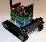
Surveyor SRV-1 Blackfin WiFi
The Surveyor SRV-1b module provides an interface to the Surveyor SRV-1 blackfin robot. The module will request images from the Robot via 802.11 WiFi and allow you to view and process the images using RoboRealm. Motor commands based on the captured images can then be sent back to the SRV-1b robot to change its direction/speed.
Interface
Instructions
1. IP Address / Port - specify the appropriate IP address (192.168.0.15) to what you have configured your SRV-1b robot to respond to. Be sure to change the default port number 100001 if you have also changed that default configuration.
2. Manual Move - there are three ways to move the robot. The manual move allows you to press the appropriate buttons and move the robot in a direction for a period of 500 ms.
3. Motors - the second way to move the robot is to move the Motor sliders that control each of the individual motors. Note that this interface is provided to map RoboRealm variables to each of the motors to enable differential steering control from your RoboRealm control program. You can use the Min and Max editable areas to limit the range of movement that the robot will be commanded to execute. Often variables may contain irregular values due to scripting error so ensuring a limit on the motor values will ensure that your robot does not suddenly dart off in an unknown direction. A slow suggested range is 90 - 160.
The motor values range from 0 to 255 with 128 being neutral or off. Higher numbers move the robot forward while lower numbers will move the robot backwards.
If you find that your robot is not moving ensure that you at least hear a 'whine'. If not increase the values being sent to a higher range and ensure that the min and max are set to allow for that higher value.
You can also try lifting the robot off from the ground and test the motor values. Once the motors do not have as much momentum to overcome they may start to move. This also indicates that the motor values are too low to cause the robot to move.
See Variable Control for more information on how to programatically move the robot.
4. Movement Variable - the final and third way to move the robot is to select
a movement variable. This variable should contain the following values which
mimic the manual move buttons. This style of automated movement control is
not are refined as the individual motor command but can be useful for
interfacing to interface devices like the keyboard or joystick.
5. Video - to view the video stream ensure that the checkbox next to the Video group is checked. This will start video streaming from the SRV-1. Select the appropriate size while keeping in mind that smaller sizes allow for more rapid updates. At an image size of 160x128 you should get more than 5 fps. Once the video is enabled you should start to see the image within the main RoboRealm interface. You can now proceed with machine vision based filters to process what the robot is seeing.
To further increase the video rate you can select a lower quality level for the video image. This will cause more compression of the image which results in fewer bytes being transferred to the PC system but also causes degradation in the image.
The "Pause for video" checkbox will ensure that while an image is being downloaded from the SRV-1 that its motors are off. This ensures that the robot does not move while it is blind. If you find your SRV-1 does not appear to be responding to visual stimuli or overshooting the target, select this button to reduce the motor speed and gain better control over the image processing and motor reaction loop.
6. Stereo - If you have the stereo version of the SRV-1 you can enable the capture of the second image by selecting the checkbox next to the Stereo group. If your SRV is configured to use a different port number specify that port number in "Stereo port number". The second image will then be captured and stored as a "surveyor_stereo" and can be accessed using the Marker module or by other modules that require additional images than the currently viewed image such as the 3D Viewer module. If you would like to quickly check the second image select the "Switch Left/Right" which will cause the second image captured to become the current image seen in the main RoboRealm interface.
7. Laser - you can test the laser lights by clicking on the "Test" button which will turn on the lasers for 5 seconds. Be sure to have the lasers pointed to a safe direction before turning testing.
To turn the lasers on and off using automatic control select a variable that when non null (i.e. it contains some text or number) the laser will turn on. Likewise when the variable is "" or is deleted the lasers will turn off.
When the lasers are turned on the Range variable will be set with the estimated distance from the robot to whatever the lasers are shining on. Note that this range variable is only valid if the lasers are turned on.
8. I/O Pins - to extend your Surveyor Robot you can use the IO Pins located on the robot to interface with other sensors or signal additional lights/LEDs/etc. To enable pin setting check the checkbox next to the I/O Pin group. The interface will then be enabled.
The GUI interface allows you to manually turn the pins off and on using the checkbox. Note that the checkbox is only enabled when the pins are set to output. The checkbox is invalid when the pin is set to input values. To automate the setting or getting of pin values assign a variable to the appropriate pin. If the pin is configured as an input then this variable will be a 1 or 0 if the input is high or low. If the pin is configured as an output then variable values of "0", "", "off", or "low" will set the pin low otherwise any other value will set it high.
9. Failsafe - to protect the robot when a loss of communication occurs the failsafe mode will ensure that the robot turns off motor commands if the wireless communication is no longer present. This can occur for a number of reasons but is normally related to the distance between the robot and the 802.11 receiver.
10. Speed - a manual selection for the speed of the robot when using the Manual Move buttons.
11. Stop - sometime the most important button in the interface is the stop button. This button will terminate the robot's movement and allow you to regain control of the robot regardless of the variables specified in the motor interfaces.
12. Servos - The base SRV robot has the ability to produce PWM signals on pins TMR2, TMR3, TRM6 and TRM7. Pins TRM2 and TRM3 are connected to the onboard motors and thus are not available for use with servos. Pins TRM6 and TRM7 are available and can drive regular PWM based servos. The Servos tab provides access to those pins and can be configured to move servos based on entering in the appropriate variable that will contain the value for those servos. Note that if you are using the SVS system then you will have 4 additional PWM signals on the second SRV board. As this board is not connected to any motors the TMR2 and TMR3 pins are available.
13. RCM Servos - For even more servos you can connect the RCM expansion board to the I2C interface of the SRV and have access up to 20 additional servo control signals. The RCM tabs provide an interface to those servos to allow them to be programmed via a variable setting.
Working with the SRV and RoboRealm
1. Ensure that you computer is connected to the SRV1b using a Peer to peer network or that the SRV1b is connected to a wireless network router. Note that you need to be sure in either case that your network address is compatible with what is being used. The SRV1b by default is configured for 192.168.0.15 which means that your computer needs to be using something like 192.168.0.X where X is anything but 15, 0 or 1. (The 0 and 1 are normally reserved for gateways and routers). If this is not the case then you can either change your computers IP address or the SRV1b's address.
Remember As Default - Select the "Remember as Default" checkbox if you would like the current IP setting to be remembered by RoboRealm such that whenever the SRV1b is loaded the IP address will be auto-populated to the current setting. This ability allows you to not have to constantly change the IP address when loading in successive RoboRealm SRV configurations.
2. Switch On The Surveyor. If you are using a peer to peer connection your wireless link indicator should go green on your computer.
3. Run RoboRealm.exe
4. Insert in the SRV1b module. The quickest way to do this is to click on the Search tab in the upper left corner and type in surveyor. The module will appear in the list below your typing. Double click on that module to insert it into the pipeline. Note that there are TWO Surveyor_SRV modules. One without the 'b' which is the old system and one with a 'b'. Chose the one with a 'b'.
5. Configure the module to use the correct IP address if you are not on a 192.168.0.X network. If you are not and you change the IP address you will have to wait a bit after you are done changing the IP address to let the current network connection timeout. Once this happens the new IP address should be accepted and a connection will be attempted. You should see a single image from the SRV1b in the RoboRealm main GUI at this point.
SVS version (Stereo SRV1b) only from this point on.
6. Click on the Stereo checkbox. If you are using a non-standard Stereo port you will have to change that setting. Again, once you do this you will have to wait for the current network connection attempt to timeout before the setting will be accepted by the application.
7. Using the Switch Left/Right checkbox you will now be able to flip between the two images coming from the SVS.
8. Close this GUI by clicking on OK and insert the 3D Viewer module (again using the search tab mentioned above). This module is used to create 3D viewing images from the two image streams coming from the SVS.
9. Click on the "Two Separate Images" radio button to tell the module to grab the left and right images from two different sources. Then select one of them using the dropdown as "surveyor_stereo" which should be the last entry in the dropdown list. You can leave the other one as "Current" as that is the other image side.
10. You will now see a color Anaglyph. You can change the viewing options using the "Type" dropdown in the Options group. For example you can view the two images side by side by selecting "Side by Side".
11. Note that the two images will most likely not be very aligned and cause difficulty in creating a stereo image. Click on the "Sample" button which will cause the module to sample 10 images and then move one of the images such that it is better aligned with the other. You can also adjust these values manually by increasing or decreasing the values as needed.
12. Finally, you might not get the correct left/right image combination so try using the "Switch Left/Right image" checkbox to switch the left and right images quickly. It does matter which way around these are so try both until you have an image that appears more 3D. Note that once you click on the Switch checkbox you will need to realign the images as switching the images throws off the alignment.
13. Note that due to the disparity of the SVS you may first want to view objects far away from the SVS which will feel more relaxed on your eyes. As objects move closer the increasing disparity will start to strain your eyes in order to keep stereo viewing.
Example
Click here to check out our tutorial on the SRV-1 blackfin following a trail of orange squares.
For more information
Surveyor SRV-1 Website (no longer available!)
| New Post |
| Surveyor_SRV1b Related Forum Posts | Last post | Posts | Views |
 Watchdog for Roborealm
Dear Stevens, Good Morning, When I use edge detection metho... |
9 year | 2 | 2970 |
|
Blackfin camera
Hello everyone! I am considering purchasing RoboRealm, but first I need to know if it is compatible... |
15 year | 4 | 4681 |
|
SRV laser and pan tilt problem
Hi all I have some problems with my SVS1b surveyor robot. First, i can't find a way to... |
16 year | 4 | 4349 |
 srv1 motors control
hi steven, my name is fabio and I want to ask your help because I'm using roborealm for the thesis at the University and I'm w... |
16 year | 7 | 5893 |
|
srv1
Dear Sir, I use the SRV1 blackfin with two servos connected to TMR6 and TMR7. Using PicoC compiler I... |
16 year | 1 | 4506 |
|
surveyor SRV
Hi Guys, Im doing a new project with surveyor SRV(carmera only). In this project, I will set the ca... |
16 year | 4 | 4513 |
|
Pan tilt svs
Hello i have a problem with my SVS surveyor robot, i can't find a way to control pan-tilt.I assemblied the SVS su... |
16 year | 6 | 4838 |
|
Compatibility of SRV-1 and Roborealm example
Hello, We're interesting in Roborealm with SRV-1. And we found a question for the t... |
17 year | 3 | 5180 |
|
Has anyone been using laser control in the SRV-1b module (RR version 2.2.12)? I created a laser variable and can togg... |
17 year | 7 | 5235 |