
Marble Maze
This Marble Maze tutorial shows how to use image processing and custom path planning to solve the maze by rolling a white marble from any starting point to a defined end point within the maze.
In this tutorial we use the setup from a partner site Tele Toyland called the Marble Maze. The goal of the Marble Maze is to command the platform from over the web to pan or tilt in order to solve the maze by moving the white marble from the start point in the maze to the end point. The trick with this installation is that you need to take into account that the ball will not stop unless there is a Lego brick in its path and that the ball does not always roll in a straight line nor stop exactly where desired. Thus while the maze does not appear to have many "walls" in the maze it is nevertheless a maze and requires some strategic thought to solve.
The task of this tutorial was to take the manual web interface and create a RoboRealm application that could solve the maze and move the ball from the start to the end. This required no additional hardware than is currently functioning. There is already an overhead camera and a servo board controller (in this case a Parallax USB servo controller) so the hardware build is already done.
The main task of automatically solving this maze is to process the image in order to create a idealized model of the maze and then solve the path planning issue using that model. Using the overhead camera we can acquire an image from the maze to process before each move is made. But first let's see what the maze looks like from the overhead camera's point of view.
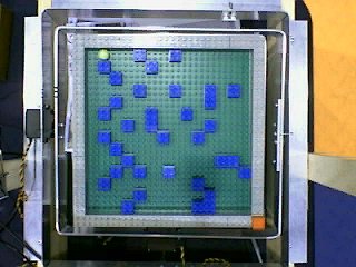
The image above shows the view from the overhead camera looking down at the maze. The main part of the maze is the green background which is the "floor" of the maze. The gray Lego blocks outline the border of the maze. The inner blue blocks are the maze walls. The white ball can be seen in the upper left corner with the destination goal in the lower left specified by the red square.
On first view you can notice that the camera is not perfectly centered above the square maze. Our ideal model of the maze would be a perfect square. In order to align the image better we have to start the image processing part of the tutorial.
Image Alignment
In order to square off the maze we use the Affine module and outline the gray square using the provided GUI interface of the Affine module. The interface will look as follows:
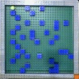
which when processing the previous maze image will align as a nice square. The resulting image is scaled to a 256x256 image (the affine module is also used to scale the image to a specified size).
Why is this needed? ..
Maze Model
To solve the maze we will need to know 3 things:
#1 is best represented (or modeled) as a two dimensional array with each array bucket containing a number that represents if the spot in the array is open (green) or blocked (blue). This can be thought of as a bitmap image with each "pixel" representing if the spot is open or closed. Note that you cannot use the image bitmap directly as there are too many pixels that represent an "open" or "closed" spot. The current image needs to be simplified to an ideal model.
#2 and #3 would then just be two x,y coordinates within that two dimensional array.
Thus the ideal maze model is a two dimensional square array. Since the maze is created using Lego blocks there are only so many blocks that can be placed in the maze. In this case the maze can contain a maximum of 14 2x2 blocks in either the horizontal and vertical direction. The array can then be a 14x14 array which is nice and small and can be quickly processed. Therefore, the first part of transforming the image into a small 14x14 array is to align the image into a square. With this alignment the image is now a scale factor representation of the array.
In order to continue the transformation we cannot simply scale the image into a 14x14 bitmap as the resulting array would contain variations of blue, green and gray pixels. This would still be hard to process as it would require a range of pixel colors to be interpreted in order to know that a current position is free or an obstacle.
Instead, the next step in our simplification process is to filter the image for the blue blocks using the RGB Filter module. We then remove small blobs as they are mainly due to noise and are not part of the blue blocks.
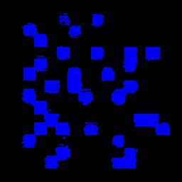
As we can see this certainly helps to isolate the blue blocks. We then scale the image down using the Scale module to a 16x16 image. For viewing purposes the following is that image scaled back up to a larger size so that we can see each individual pixel.
We can see that the blocks are better defined (in terms of accuracy) but we still need a blocked/unblocked signal instead of a varying gray value. We can do this by thresholding the image. We also crop the image as the border pixels are not needed. This creates a 14x14 sized image.
With the final threshold we can see the blocks nicely defined within a grid. This image can now be accessed as a 14x14 bitmap image which will have an RGB value of blue (0,0,255) in those positions where a blue Lego block occurs otherwise each pixel will be zero (black color).
If you notice closely you will see a single blue block in the lower part of the image being represented as two blocks instead of one. This is due to a single block being offset outside of the 2x2 grid. This breaks our 2x2 alignment requirement but is included to illustrate what happens when this requirement is not met.
Now that we have the idealized grid model let's find out where the ball is!
Where's the Ball
Given our original image we now need to process the same image for the white ball. We can revert RoboRealm to the original image by using the Marker module to save the current image and revert the viewable image to the aligned source image.
We'd like to separate the white ball from the rest of the maze. The first step is to collect all the white pixels into a blob that can be processed at a higher level in order to determine which one is the white ball. We start this by using the Flood Fill module.
This helps to group pixels into like colors. Note that as the white ball is considerably higher in intensity from the rest of the image we can use a very large threshold value. While this causes the green and blue colors to merge it does keep the ball separate from the background. As we have already processed for the blue blocks we are not concerned about this green blue color merging. Now we can separate each of the blobs using the Blob Separate module so that they can be processed individually.
we can process the image for the strongest circles using the Circles module. Note that using the flood fill module to first group like pixels as apposed to just detecting edges straight from the source image as is normally used as a precursor to the Circles module helps reduce the amount of false circles detected. False circles might be detected due to lighting changes that momentarily cause a circle to be seen.
Once the circles are detected each circle is filled with the mean color of the pixels that makeup that circle using the Blob Colorize module and checked to see that this value is high (i.e. towards white). This blob removal processing is done by using the blob filter module. What we are left with is a single circle that best represents where the ball is (i.e. it is a white circle). The center of gravity of this circle is then considered to be the X and Y coordinate of the ball. Note that this coordinate is also divided by 14 in order to ensure that the values are within the range of the previously created 2x2 dimensional array that represents the maze.
Next we move to the destination square. This is easily determined by filtering the image for red once again using the RGB Filter module and then filtered for the largest red square using the Blob Filter module as seen in the image below. The resulting center of gravity coordinates of the red blob is then also scaled into the 14x14 array.
Now that we have all the information we need we have to determine how to calculate the route from where the ball is to the destination red square using a custom ball rolling path planning algorithm.
Ball Rolling
The trick to understanding how the ball moves is to assume the ball will roll in more or less a straight line and stop only when colliding with a blue block or the gray border. This action can be simulated in our model by using a search along a specific horizontal or vertical line for as long as the value of our model or array is zero.
As the ball may not stop or roll in the manner that we expect we only need to make a single move, restore the maze to horizontal and then take another picture to see what has actually happened. Despite the need for only the very next move we still need to determine the entire path from the white ball to the destination as the next move can only be calculated by knowing the entire route.
We calculate this path by starting at the balls current location and start searching in all the 4 possible directions for the next stop. As we only assume north, south, west and east ball movements we only need to check the possibility of the ball rolling in those directions. This process then repeats in each of those 4 new locations for the next 4 and so on. By checking if any of those new locations is the destination we can search the entire maze for the quickest way to get to the destination, i.e. the red square destination coordinates terminate the search.
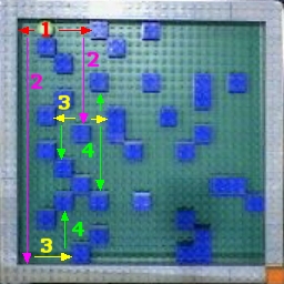
The above image show the first four search levels. Note that at every stop point all those directions (other than the one just came from) are explored if there is no obstacle present in that spot in the array. This expansion can increase the total number of search paths quite quickly, however, as we have a relatively small maze this is not currently an issue and no search pruning is required.
The actual algorithm is known as a breadth first search as it will guarantee that the shortest solution (the one with the least ball rolls as apposed to actual distance) will be found first. This algorithm is done in VBScript and implements a queue structure for the search. As each new stop location is found it is added to the queue. The queue then grows with new search locations being added to the end with the top of the queue being the point of new exploration.
See the commented VBScript code contained in the VBScript module for further details.
Marble Maze
Video
Video of the marble maze being autonomously solved even with a large roll error.
Results
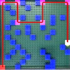
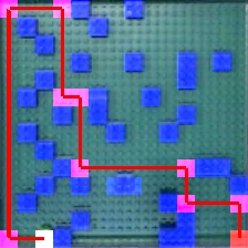
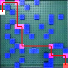
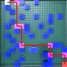
The following are image captures of the final route as determined by the image processing and route planning. The white square is ontop of the ball, the red square is the location closest to the destination red square and the purple squares are the direction changes due to the blue stops in the maze. The path is shown in red that proceeds from the white square to the red square. Note that this planning is performed after every move in case the ball rolls in an irregular direction or bounces off from the blue/gray blocks due to roll momentum.
Issues
Alignment
The alignment of the square maze is key to the correct processing of the maze. With minor misalignment some of the blue squares may bleed into neighboring areas and cause a false obstacle to be detected. This may or may not cause an issue with the maze depending on if the found route depends on that obstacle. If the solution found requires that the blue block exists then it may cause the system to oscillate around a nonexistent solution. In addition, the false detection of the blue block may cause the maze to be defined as unsolvable (i.e. the image will be set to all white).
Lighting
Other issues are due to lighting. Lego blocks and surfaces are actually very reflective and can cause substantial lighting halos that cause the detected color to become over saturated and not detected. This is an issue for all detected objects (blue blocks, white ball, and red destination object). To counteract this issue the maze is tilted slightly i.e. is not perfectly horizontal when the overhead camera takes the maze picture. This slight tilt helps to reduce the glare typically produced by overhead lighting.
Robustness
Despite many of the inaccuracies that can develop in the system (such as the calibration going out of phase) the system is quite robust in that after each move of the ball the entire course is recalculated in order to know the next move to make. Due to this errors that happen due to lighting or even the ball not rolling correctly (as seen in the above video) the end goal is still accomplished as any move will change the dynamics of the system. As long as the system performs more correct than wrong analysis the goal should be achieved.
Failsafe
In some cases the ball may accidentally get stuck in a strange location between the Lego blocks. In this case the system detects this situation to see if the ball coordinate is different than the last time. If the ball has not moved the VBScript module will command both the pan and tilt servos to move with a larger than normal value in an attempt to "free" the stuck ball. Note that when this happens the goal direction is ignored until the ball is found to be free and moving again. This process, while rare, helps to ensure the system has failsafe.
Pipeline
The following is the processing pipeline as seen within RoboRealm to accomplish the marble maze solution.
Notes:
1. You can enable the Parallax controller module if you have the Parallax servo controller. (The robofile has that module disabled on load) If not you will need to replace that module with your appropriate controller. This configured servo controller module assumes that you have two servos attached to the controller to move the tilt and pan of a platform like the Marble Maze.
2. The speed of the system is currently constrained by the time it takes for the marble ball to roll from one side of the maze to the other. Currently the algorithm waits a set amount of time regardless of how long the ball actually needs to roll. An improvement would be to monitor the image and right the maze back to horizontal once no more movement is detected, i.e. the ball has stopped rolling ... but we will leave that improvement to you!
3. The core of the path finding algorithm is in the VBScript module. The VBScript essentially processes the image as a 14x14 pixel array accessed directly in VBScript. Within this code there is a lot of additional code used to generate the final graphic seen above. Keep in mind while looking at this code that a lot of it is not necessary for the actual functioning of the algorithm. Only the very next move needs to be store and not the entire path. The entire path is recorded, however, in order to show graphically what route is currently being attempted.
Your turn ...
Want to try this yourself? Following is the robofile that should launch RoboRealm with the original image we used in this tutorial. You can click on each of the steps in the pipeline to review what the processing looks like up to that point. Note that if you disable the first conditional you can highlight each successive modules to see how the image processing is performed. The first conditional in the pipeline is to ensure that the system only updates the ball path when needed (i.e. the servos have completed their move) such that the system can easily run on a slower platform.
The End
That's all folks. We hope you've enjoyed this little adventure into an application of machine vision processing. If you have any questions or comments about this tutorial please feel free to contact us.
Have a nice day!
| New Post |
| Marble Maze Related Forum Posts | Last post | Posts | Views |
 marble maze
question. in this tutorial of marble maze. what are the type of servo motor is used? ... |
13 year | 7 | 5118 |