
Automatic Image Calibration
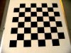
The Automatic Image Calibration module provides an easy way to quickly calibrate an image view based on a rectangle calibration grid. The module expects a rectangular checkered grid of any size to be visible in the image. Once the grid is detected the module will warp the current image such that the grid will become square within the image. Namely, each checker box will be the same number of pixels regardless of rotation from the camera imaging plane. This ensures that objects within the calibration plane will be the same relative size. This can also be used to independently calibrate two separate images to be combined into a single larger image.Once calibrated, the checker board can be removed and the transform will remain such that any objects on the same plane will be transformed in the same way as the grid was.
If you select the "Show Detected Grid" checkbox you should see a green overlay on the recognized grid. By pressing the calibrate button the image will be automatically warped such that the checker grid will be square with respect to the image plane. This warping process will remove perspective, scale, and lens distortions that can cause problems when measurements or recognition tasks need to be performed on surfaces not aligned to the imaging plane.
This module has two functions, one to determine calibration parameters based on a checker board calibration grid and then to warp subsequent images to that setting. Thus the intended use is to first calibrate your camera using a calibration grid and then have all subsequent images be transformed in the same way as the calibration board dictated.
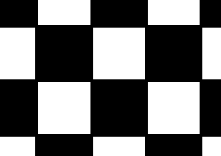
If you need a checkerboard grid to print out you can use this one. If you are using a very wide angle camera and need to place the grid very close to the camera a finer checkerboard grid is probably required..
Interface
Instructions
1. Square Size - This setting indirectly affects the size of the image. The specific property refers to how large one of the checkered squares should be made in the resulting image. By choosing a convenient number you can also ensure a simple real world to pixel coordinate conversion. For example, if your square is 1 inch long and you set the square size to 20 pixels then each pixel will represent 0.05" in real world. Taking any measurement in pixels from the image thereafter can be multiplied with 0.05 (1/20) to get real world inches.
2. Intrinsic Transform Only - If you are just interested in removing lens distortion properties of the image you can select that only intrinsic transformation be applied to the image. This will retain scale and perspective but remove the pincushion or barrel warping of the image.
3. Realtime Calibration - If you are not sure on how the final image looks with regards to a particular orientation of the calibration grid you can select the Realtime Calibration which will calibrate the image to the visible checker grid as-fast-as-possible to allow you to settle on an appropriate view. Note that this will create a very slow frame rate as the calibration process will not permit a very high frame rate. Once you are happy with the image you can unselect this checkbox and the frame rate will dramatically increase but still warp the image as appropriate.
4. Precise Calibration - If your application requires very precise calibration select the "Precise Calibration" checkbox to increase the calibration precision. This *will* really slowdown the calibration process as the module will attempt high precision alignment at the cost of additional computing. This ONLY affects the calibration time but will not change the time required to warp images into the calibrated image once calibration is done.
5. No Rotation, Rotate 90, 180, 270 Degrees - Since the calibration grid does not have a obvious orientation there are cases where when calibrated the image will be incorrectly oriented with respect to this 90 degree ambiguity. You can select the appropriate rotation to correct for this ambiguity.
6. Command Variable - Specify a variable that contains "calibrate", "intrinsic", "extrinsic" or "reset" to command the module to perform those calibrations. This is typically used when external applications need the module to recalibrate automatically (via the API) without needing a user to press any of those buttons.
5. Pixel/Bilinear Resample - If you need quicker but a less precise/smooth transform you can select "Pixel Resample" which will perform the resulting image transformation quicker but with a blockier feel.
7. Show Detected Grid - Select if you are not sure if the calibration grid you are holding is being detected by the module. Keep in mind that reasonable lighting and size are expected in order to calibrate correctly. Any image containing a grid whose squares are less than 20 pixels in size in the image will probably NOT be detected.
8. Show Model Grid - Select to see how well the calculated model fits the actual model. With both Detected and Model Grid checkboxes selected you can compare the purple versus the blue circles to see which points are problematic and not modeled accordingly.
9. Error - Provides an indication of how well the lens model was fitted to the current grid. Most alignments will fit below 1.0 but if a large grid is used with many squares this number will be larger. You can use this number to determine what configuration gives the best fit and thus the most accurate modelling of the grid.
10. Extrinsic Parameters - Those values calculated given the calibration grid that will warp the image to align the calibration grid with the imaging plane. Note that you can chose to view the rotation as degrees or radians.
11. Intrinsic Parameters - Those values that best describe the lens distortion present in the calibration image. These parameters describe the pincushion or barrel warping obvious in less expensive len's but may also be subtly present in any camera.
12. Parameters - Since you will typically only calibrate once and then reuse those parameters in different robofiles for the same camera you can export and import all the parameters into the module without needing to recalibrate. By press the EXPORT button, you can select a file to save all the needed parameters into. This file will contain all the variables below that specify the specific transform.
Once these have been exported, you can specify that same file in the Import filename to import those back into this module without needing to recalibrate. Note, if this file changes the system will update its transform accordingly.
In this way, you can configure multiple cameras with different configuration files which allows for a central robofile configuration to update updated without corrupting calibration values that will differ for each camera.
13. Calibrate Both - Calibrates both Intrinsic and Extrinsic parameters based on the current grid in view.
14. Calibrate Intrinsic - Calibrates just the Intrinsic parameters (lens distortion) based on the current grid in view.
15. Calibrate Extrinsic - Calibrates just the Extrinsic parameters (grid position) based on the current grid in view.
16. Reset - Resets all parameters to their default values.
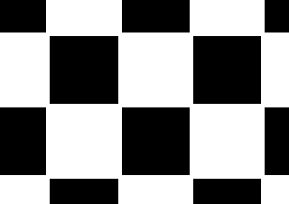
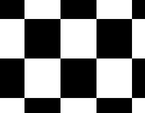
Example
| Source | Calibrated Image |
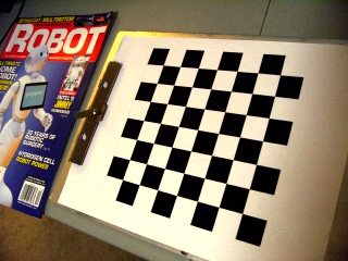 | 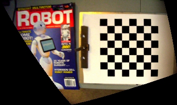 |
 |  |
Notes
For best results
- Use as large a calibration grid as you can to cover most of the image. Smaller grids will not capture the lens distortion parameters well enough as they are mainly pronounced at the image edges.
- Avoid using grids that are out of alignment by more than 45 degrees as that will start to distort the squares too much for an accurate rectification.
- Ensure that the grid is a matte (non-reflective) surface (like printed blank ink) otherwise the square detection will not work very well.
- If you have detection issues enable the grid display and move the grid around a little until you see the green overlay.
- Ensure that each square is at least 20+ pixels big otherwise they will not be detected. Try moving the grid closer to the camera to see if that helps with detection.
- Avoid any shadows that would break the grid into shaded and non-shaded parts.
- Ensure that there is sufficient contrast (white is much whiter than black) in order to get the most precise position information.
- Keep the calibration grid as flat as possible. If you print something out paste it onto a more solid surface to ensure it remains planar. If you happen to have a chess set lying around the board makes for a good calibration grid!
Also note that the grid size is auto-adjusted for. You can use a 12x12 or a 6x18 grid without changing any parameters.
Common issues with the calibration grid are when its printed. Be sure that the squares of the grid intersect at a single point. Also be sure that each square is actually square and NOT rectangular. The entire grid can be rectangle in shape but each individual square MUST be the same size.
Variables
AUTO_CALIBRATION_ERROR - The average pixel distance error between the image
	grid and the matched warped grid	based on the calculated values
AUTO_CALIBRATION_X_TRANSLATION - The horizontal translation from center of
	screen the detected grid is at
AUTO_CALIBRATION_Y_TRANSLATION - The vertical translation from center of screen
	the detected grid is at
AUTO_CALIBRATION_SCALE - The size difference between the desired square size
	and the actual detected square size
AUTO_CALIBRATION_PERSPECTIVE - The focal length used to unwarp the detected
	grid to bring it back to the	image plane
AUTO_CALIBRATION_X_ROTATION - The radian amount of pan rotation to bring the
	grid back into the image plane
AUTO_CALIBRATION_Y_ROTATION - The radian amount of tilt rotation to bring the
	grid back into the image plane
AUTO_CALIBRATION_Z_ROTATION - The radian amount of in plane (orientation)
	rotation to bring the grid back	into vertical/horizontal alignment
AUTO_CALIBRATION_K0 - The K0 camera property used to invalidate len's distortion
AUTO_CALIBRATION_K1 - The K1 (multiplied by radius) camera property used to
	invalidate the lens distortion
AUTO_CALIBRATION_K2 - The K2 (multiplied by radius^2) camera property used to
	invalidate lens distortion
AUTO_CALIBRATION_KS - The K scale/zoom factor used to invalidate len's distortion
AUTO_CALIBRATION_U0 - The X principal location (Cx) of lens distortion center
	with respect to center screen
AUTO_CALIBRATION_V0 - The Y principal location (Cy) of lens distortion center
	with respect to center screen

AUTO_CALIBRATION_CORNERS - The X,Y coordinates of the found corners of the
	checkerboard or points provided that are used in the calibration process.
AUTO_CALIBRATION_CORNERS_WIDTH - The number of coordinates found in the horizontal
	direction of the checkerboard. Note to due to failure of detection this can be
	less than the total checkerboard size.
AUTO_CALIBRATION_CORNERS_HEIGHT - The number of coordinates found in the horizontal
	direction of the checkerboard. Note to due to failure of detection this can be
	less than the total checkerboard size.
See Also
Radial Calibration
Perspective Calibration
Transform Image
Affine Warp
Bottle Unwrap
For more information
Camera Calibration Toolbox for Matlab
Sentience Camera Calibration
tclcalib - A tool for camera calibration
| New Post |
| Auto_Image_Calibration Related Forum Posts | Last post | Posts | Views |
|
Track object and measure thickness
Could anyone briefly let me know how to track a dynamic object while measuring its thickness repeatedly? | 8 year | 2 | 3479 |
 3D measurement
Hi, steven, I wonder if Roborealm could measure the length, width and height like the pic... |
8 year | 2 | 4085 |

I want to unwarp my images with "Intrinsic and Extrinsic Parameters", which are obtained from "Automatic Image Calibration" with... |
9 year | 10 | 5459 |
|
Automatic Image Calibration
Hello, I am trying to run Roborealm on a Kangaroo for a project where I need to identify the specific location of ... |
9 year | 5 | 4247 |
|
automatic image calibration parameters
I want to do automatic calibration in one script, and then load these calibration parameters and warp images when I run another ... |
9 year | 6 | 4216 |

Hello, I am trying to use Automatic Image Calibration, but I'm having difficulty. I have... |
9 year | 2 | 4252 |
|
The attached robofile illustrates two odd behaviors. 1) The auto calibration will not work on the o... |
9 year | 3 | 4055 |
 X, Y List variable
What parameters are transmitted in Automatic Image Calibration Module into the Calibration Type > X, Y List variable? | 10 year | 2 | 3998 |
|
what is COG_X in auto image calibration
in automatic image calibration dialog box, what is the calibration type: COG_X COG_Y? I do not see description in help. ... |
10 year | 2 | 3968 |