
Line Probe
The Line Probe module provides a way to extract out a line from a given image assuming that the placement of the probe is in the approximate location of the line's edge. This module is used in machine vision quality assurance techniques in order to determine if a particular part meets specific quality assurance levels. For example, if your part requires that a side of the part needs to be a particular slope or intersect another line at a particular point then the Line Probe module can be used to extract out that line. The variable array then contains the start and end coordinates of the line which can then be examined by other modules or exported to external applications.
Interface
Instructions
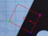
1. Current Image - move the probe graphic to the location which you want to probe for lines. You drag the red square to move the entire probe or move each of the corners to change the shape and size of the probe. Note that the arrow dictates the search direction and should always be perpendicular to the edge being detected. You can also move each endpoint individually by changing the coordinates using the text boxes below in the Coordinates area.
Use CTRL-click to move the entire probe to a different location. Use SHIFT-drag to create the probe of a certain size in the clicked position. When zoomed in, drag the image around to view different parts of the image or expand the dialog window to view more of the image.
2. Use Origin - You can specify that the current coordinates are relative to the Origin Variables created by the Origin Probe Module (or by setting these variables yourself). This allows the specified coordinates to move relative to the detected origin in case what you are sampling is not always in the same absolute image location. When you select this checkbox the current origin values are subtracted from the currently specified coordinates to create a relative position. If you have not yet set the origin, you can come back later and adjust the coordinates as appropriate.
3. Options Identify - select how many lines you want to detect. Note that if you select many lines to be identified you are not guaranteed to get that many lines depending on the thresholding information below. The "Identify" number specifies a maximal number of lines to detect.
4. Smooth Edge - to reduce noisy edges select the amount of smoothing that should be applied to the edge prior to edge detection.
5. Line Isolation - to avoid multiple lines from being detected together select how many pixels each line's center should be isolated from the next detected line center.
6. Edge Threshold - to eliminate very weak edges from being detected as part of a line select an appropriate edge threshold (0-255) that will remove edges whose edge intensity is below the threshold. Note that smoothing the edge will also reduce the edge intensity and thus the Edge Threshold will need to be adjusted after the smoothness is specified.
7. Relative Threshold - to only select those edges that are significant you can specify the relative threshold (0-100) that will remove successive edges that are the relative threshold percent less than the previous edge. For example, consider the highest 3 edge values as 130, 120 and 40. If the relative threshold is 50% then the last edge 40 would be eliminated since 40 is less than 50% of 120. As 120 is 92% of 130 it is not eliminated (unless the threshold where set at 95%).
8. Show lines - to visually see which edges are detected (in the main RoboRealm interface) select the appropriate Color and Thickness of the line that will indicate where in the image the edges have been detected.
Example
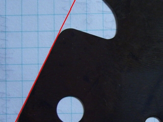
| Detected line using above probe |
 |
Variables
PROBED_LINES_COUNT - the number of lines detected.

PROBED_LINES - an array consisting of the X_START, Y_START,
X_END, Y_END of each detected line.

PROBED_LINES_POINTS - an array consisting of the X, Y coordinates of
each detected edge point that was used to calculate the lines.
See Also
Origin Probe
Edge Probe
Circle Probe
| New Post |
| Line_Probe Related Forum Posts | Last post | Posts | Views |

hi. I`m new to roborealm. I want to draw a offset line to probed lines count variable (a line drawn to probed lines count variab... |
10 year | 4 | 3207 |

hello, i have been working with thickness and line probes but i still have not figured out how to work and position the probes.... |
16 year | 6 | 5267 |

Hello, I would programmatically use the edge probe to check the alignment of a blob/object. &n... |
17 year | 3 | 5009 |