
Origin Probe
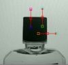
The Origin Probe module allows you to specify a reference position that can be used in other probe modules to specify relative placement based on the origin. This is useful if you cannot use long measurement probes with your object due to size constraints but can use long probes to create a reference position. This enables the system to compensate for large movements without compromising measurement positioning.The three probes are means to be used to specify two lines whose intersection is considered the origin or 0,0 position. Use the two probes to specify the X axis and the third to specify the Y axis. By dragging the probes around your image you will see the generated axis lines in the main RoboRealm window being generated. Once complete you can then add additional probe modules into the processing pipeline and select the "Use Origin Variable" within that probe to base its position from the origin specified in this module.
Interface
Instructions
1. Current Image - move the three lines such that they specify the 0,0 location correctly. Note that the two parallel lines should be used to specify a single axis with the third being used to specify an orthogonal axis. You can use the red square to move the entire line, the endpoint squares to move each endpoint individually or change the coordinates using the text boxes below in the Coordinates area.
Use CTRL-click to move the entire probe to a different location. When zoomed in, drag the image around to view different parts of the image or expand the dialog window to view more of the image.
2. Precision - the precision specifies how each pixel should be divided in order to determine the exact place that the edge occurs. If you have a blurred image you may need to reduce the precision to negative numbers. Negative numbers mean that a edge is comprised of several pixels (i.e. white to black transition occurs slowly over several pixels). If positive the precision will determine where the edge most likely exists between two successive pixels by interpolating values between the two pixel intensities.
3. Smooth Edge - to reduce noisy edges select the amount of smoothing that should be applied to the edge prior to edge detection. This prevents a single sharp noise pixel from being detected as an edge.
4. Probe Types - Specifies how the points within each probe are located.
5. Link Probe 3 - Specifies that probe 3's (orange to white) position is relative to the line found by probe 1 and 2. The reason for this is that a small corner may not be easily detected if rotation of the part is present. Linking the probe to current results allows for smaller corners to still be detected through a larger range of rotation.
6. Edge Threshold - to eliminate very weak edges or pixels select an appropriate edge threshold (0-255) that will remove edges whose edge intensity is below the threshold and pixels whose intensities are below the threshold. Note that smoothing the edge will also reduce the edge intensity and thus the Threshold will need to be adjusted after the smoothness is specified.
7. Set Origin Translation/Rotation - By default the origin probe will set both translation and rotation variables (ORIGIN_X, ORIGIN_Y, ORIGIN_ANGLE) but sometimes only one or the other is needed. For example, depending on your particular image the angle may cause more vibration than it benefits. These checkboxes allow you to disable the setting of these variables to avoid undue noise.
8. Show Points - to visually see which edges are being detected select the appropriate Shape, Color and Size of the marker that will indicate where in the image the edges have been detected. Note that this appears in the main RoboRealm GUI window.
9. Show Axis - Specify the color you want to use to show the origin reference frame in the main RoboRealm GUI window.
10. Probe Coordinates - To fine tune the probe positions you can type in numbers into the appropriate coordinate boxes (they are labeled with the color of the box as seen in the Current Image area) or use the up/down spin controls to increment or decrement the numbers accordingly. Note that the text box colors correspond to the probe drag square colors.
11. Variables - The variables generated specify the translation and rotation needed in order to create a position relative to this new origin. The three variables are then used by other modules to create the reference position. Note that you can also generate or modify these variables in other modules as needed as they are just regular RoboRealm variables.
Variables
ORIGIN_X - the X (horizontal) offset of the generated origin
ORIGIN_Y - the Y (vertical) offset of the generated origin
ORIGIN_ANGLE - the radian angle (rotation) of the generated origin
See Also
Circle Probe
Line Probe
Edge Probe
Thickness Probe
Peak Valley Probe
| New Post |
| Origin_Probe Related Forum Posts | Last post | Posts | Views |
| None |