
Edge Probe
The Edge Probe module provides a way to detect edges along a specified path. The path is a single line that you can manually place on the image or control the position using variables. The edges detected are then saved into a variable for later usage. Note that the detected edges are with respect to the line angle.This module is useful for detecting the placement of a particular object within an image or to detect that a certain number of edges need to be present in the form of a component quality assurance.
Interface
Instructions
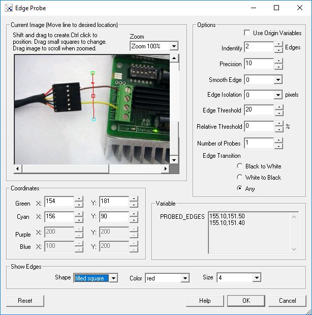
1. Current Image - move the line to the location along which you want to probe for edges. You can use the red square to move the entire line, the endpoint squares to move each endpoint individually or change the coordinates using the text boxes below in the Coordinates area.
Use CTRL-click to move the entire probe to a different location. Use SHIFT-drag to create the probe of a certain size in the clicked position. When zoomed in, drag the image around to view different parts of the image or expand the dialog window to view more of the image.
2. Use Origin - You can specify that the current coordinates are relative to the Origin Variables created by the Origin Probe Module (or by setting these variables yourself). This allows the specified coordinates to move relative to the detected origin in case what you are sampling is not always in the same absolute image location. When you select this checkbox the current origin values are subtracted from the currently specified coordinates to create a relative position. If you have not yet set the origin, you can come back later and adjust the coordinates as appropriate.
3. Identify - select how many edges you want to detect. Note that if you select many edges to be identified you are not guaranteed to get that many edges depending on the thresholding information below. The "Identify" number specifies a maximal number of edges to detect. Note that detected edges are ordered as they are encountered. The Arrow appearing in the modules GUI indicates which direction the edge probe proceeds. For mulitple probes, the first probe line is the line connecting Cyan to Green with the Purple to Blue line being last.
4. Precision - the precision specifies how each pixel should be divided in order to determine the exact place that the edge occurs. If you have a blurred image you may need to reduce the precision to negative numbers. Negative numbers mean that a edge is comprised of several pixels (i.e. white to black transition occurs slowly over several pixels). If positive the precision will determine where the edge most likely exists between two successive pixels by interpolating values between the two pixel intensities.
5. Smooth Edge - to reduce noisy edges select the amount of smoothing that should be applied to the edge prior to edge detection. This prevents a single sharp noise pixel from being detected as an edge.
6. Edge Isolation - to avoid edges from bunching up together select how many pixels each edge should be isolated from the next detected edge.
7. Edge Threshold - to eliminate very weak edges select an appropriate edge threshold (0-255) that will remove edges whose edge intensity is below the threshold. Note that smoothing the edge will also reduce the edge intensity and thus the Edge Threshold will need to be adjusted after the smoothness is specified.
8. Relative Threshold - to only select those edges that are significant you can specify the relative threshold (0-100) that will remove successive edges that are the relative threshold percent less than the previous edge. For example, consider the highest 3 edge values as 130, 120 and 40. If the relative threshold is 50% then the last edge 40 would be eliminated since 40 is less than 50% of 120. As 120 is 92% of 130 it is not eliminated (unless the threshold where set at 95%).
9. Number of Probes - at times you may want to sample edges along a path using more than one edge probe. When you increase the number of edge probes beyond 1 the probe selector area will define a box where as you increase to more probes additional edge probes will be created within that rectangle. By increasing the probe count you can quickly probe a larger area to sample more potential failure points without having to add more modules. Note that if you need multiple probes in different seconds of the image you can add more probe modules and specify a query area for each.
10. Show Edges - to visually see which edges are being detected select the appropriate Shape, Color and Size of the marker that will indicate where in the image the edges have been detected. Note that this appears in the main RoboRealm GUI window.
Note
To control the line location using variables specify the variable as [variable_name] within the coordinate textboxes.
Example
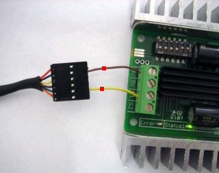
The detected edges marked with red squares using the configuration shown in the above screenshot.
Variables
PROBED_EDGES_COUNT - the number of edges found

PROBED_EDGES - an x,y array of the location of the detected edges.

PROBED_EDGES_DISTANCE - the distance between the first detected edge
  and the last. This defines the width in pixels between the outer
  detected edges.

PROBED_EDGES_MAX_DISTANCE - the max distance between the first detected edge
  and the last for each probe when multiple probes are used.

PROBED_EDGES_MIN_DISTANCE - the min distance between the first detected edge
  and the last for each probe when multiple probes are used.

PROBED_EDGES_MAX_INTENSITY - the max intensity of a pixel encountered along a probe.

PROBED_EDGES_MIN_INTENSITY - the min intensity of a pixel encountered along a probe.
See Also
Origin Probe
Line Probe
Circle Probe
Sample Line
| New Post |
| Edge_Probe Related Forum Posts | Last post | Posts | Views |

Hi! I'm having some issues with the edge probe module. I have three sequential probes (with differ... |
11 year | 12 | 4473 |

Hi! I have a little problem... I am trying to find min_x and max_x value on a speciefied Y (for example COG_Y). I... |
16 year | 6 | 7548 |