
Optical Flow
The Optical Flow module is used to determine the movement of objects from the current image with respect to the last image. Note that this means more than one image is needed in order to use Optical Flow.The Optical Flow of an image is defined as how parts of the image (in this case square patches) move with respect to the previous image. Each part of the image is broken into square patches and searched for the best match within the previous image. Once the best match has been identified a connection between where that patch current is and where it was is draw as a line. These lines are often referred to as needles due to their appearance when viewed in a moving image.
While very powerful the optical flow technique does suffer from some fundamental issues. One such issue is the nature of the matching that is performed on each patch. If there is not enough texture or pixel intensity changes within a given patch that patch could potentially match many patches in the previous image. Thus if a patch would match with too many previous patches the match would be very unstable, not contribute much to the overall flow and therefore is eliminated from the result. This eliminations causes large flat planar areas (such as in the middle of a white piece of paper) to not indicate optical flow. It becomes apparent that optical flow really likes edges and corners as the matching of those image features are more often unique than other parts of the image.
Optical flow can be used to calculate the overall image movement. At times this is needed as often the camera is stationary with a moving object in view. But in the case of a moving camera the overall global flow will "hide" objects moving against the motion of the camera. The issue is to eliminate the global flow in order to isolate the localized object motion. This procedure of calculating the egomotion or global motion can be done using the checkbox seen in the GUI interface.
Interface
Instructions
1. Patch Size - The size of the patch to match in the current image to the previous image. Note that the larger the patch the better and more unique the match will be but the flow will be slower to calculate and less precise.
2. Search Window Size - The size of the search window in the previous image in which to look for the current patch. It is assumed that a patch in the current image will be found in a similar but not exact location in the previous image. The Search Window Size specifies how much of that surrounding space will be searched. The larger the window the more likely the patch will be found but this will increase the CPU requirements and therefore decrease the frame rate. If you notice a lot of errors in the flow try increasing the search window size. If you notice a slow frame rate try reducing the search size assuming your flow is relatively small.
3. Spacing - As it is not necessary to calculate the flow for every pixel in the image (as the CPU requirements would be too great) the spacing will only process every X pixels for their flow. This in effect reduces the resolution of the flow but can increase the frames per second.
4. Precision - In addition to spacing, you can specify a lower precision for flow detection which will further reduce the search requirements by moving the search window over multiple pixels at a time instead of 1 (High). For Medium, 1 pixel is skipped, for Low, 3 pixels are skipped.
5. Eliminate Global Flow - Eliminates the egomotion or global flow of the image to reveal objects that are not moving in coordination of the global flow. An example of this is happens when you pan the camera to the left and a person is walking to the right.
6. Min Error - Before a patch in the current image is matched with the previous image a quick check to determine if the image under the patch has actually changed is performed. If the error between this patch and the patch at the same location in the previous image is below the Min Error the patch is determined to have not moved and is disregarded from the flow. If you see changes to an image with no optical flow being performed try to reduce this value. If you require increased frames per second try increasing this value as it will allow the optical flow calculation to only focus on those patches that have moved by more than a small amount.
7. Max Error - When each patch is matched an error is calculated that determines the goodness of fit. Often a patch in the current image CANNOT be matched well in the previous image. This happens in many cases but is often related to objects overlapping each other or suddenly moving off screen. The Max Error defines the maximum error that is allowed in order for two patches to be considered a match. If you notice that there are many bad needles being created try decreasing this value. Increase this value if areas of the image that are changing are not generating any optical flow.
8. Needle Color - The color of the drawn optical flow needles
9. Vector Color - As an additional graphic an overall vector (average) of all the small needle flows is calculated. This is useful if you are trying to determine the direction of how an object in view is moving with respect to the camera. The Vector Color specifies in which color this vector is drawn.
10. Block Color - Instead of viewing the optical flow as needles you can also chose to view the patch movements in an intensity mode. Select the appropriate color to view each block movement amount as an intensity value.
11. Overlay On - Specify which image the graphics would be draw on.
12. Display as Annotation - Select if you want the graphic to be draw after all processing has been completed. If this is NOT selected then the next module in the processing pipeline will see the graphic as if it were part of the image and process it accordingly.
13. Axis Restriction - If you are expecting movement only in a particular direction such as Vertical up and down movement you can restrict the optical flow checking to a particular axis. Axis restriction helps to eliminate those incorrect needles by enforcing movement checks only in the specified orientation. These irregular needles are mainly due to image noise but requires some knowledge about the potential image movement.
14. Filter Length - You can remove those needles that are too small or too long depending on the expected movement. For example, with sufficient image noise a lot of small one or two length needles may be creating. Setting a min of 3 would eliminate those needles and clean up the reported needle array.
15. Filter Orientation - Similar to filter length, the Filter Orientation will remove those needles that are not off the specified orientation. For example if you want to focus on North East needles you would use min = 40 max = 50 to eliminate all needles are that not within 40 to 50 degrees. Note that this is functionally similar to Axis Restriction above but allows for the needles to chose the closest match in any direction and then be removed if not matching a desired orientation. The Axis Restriction will ONLY match needles in the specified direction regardless of if a better match is in a slightly different orientation.
Example
| Source | Optical_Flow |
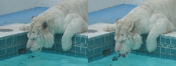 The lion is sipping at the water. Only the head is moving but camera angle was shifted. | 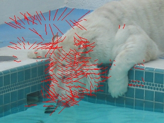 |
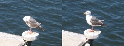 The bird's head moved from being tucked under its wing. Note that the water in the background required the min error to be set very high due the time difference between shots | 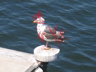 |
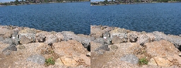 Almost stereo shot of the beachfront. Note the nice linear movement of the rocks but noise in the water. Again, due to the time different in shots the water has changed texture. | 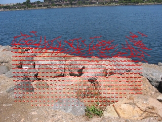 |
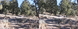 Moving fotward down a forest path. Note the expanding optical lines showing a zooming motion | 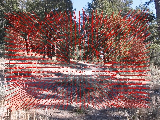 |
Variables
OPTICAL_FLOW_NEEDLES - An X_START,Y_START,X_END,Y_END list of lines that specify the start and stop coordinates of each optical flow needle. Note that this array is modulus 4 which means that each needle information occupies the next 4 numbers.
OPTICAL_FLOW_VECTOR_X, OPTICAL_FLOW_VECTOR_Y - The X,Y coordinate of the global vector that was calculated as the average from all the needles.
See Also
Movement
For more information
Optical Flow Based Robot Navigation
FlowJ - Optical Flow in Java
University of Texas - Jonathan Mugan on Optical Flow
Stanford AI Lab
| New Post |
| Optical_Flow Related Forum Posts | Last post | Posts | Views |
|
Optical Flow algorithm
Anybody know the specifics of the optical flow algorithm used by roborealm? Would like to learn more about the actual... |
12 year | 2 | 3379 |
|
I am not seeing in the Optical Flow needles array what I expect. In the array I see in my CScript module the X_END & Y_END value... |
13 year | 2 | 3325 |
|
Automatically image learning
Hi guys, I want to build a robot capable of recognizing objects in its surrounding. I s... |
14 year | 14 | 5230 |

Hello, I would like to use the Optical Flow module to track a moving object even when the camera it... |
16 year | 11 | 6327 |
|
Optical Flow Module hanging RoboRealm 2.14.1
Hi STeven, I'm getting consistent locking up in RR 2.14.1 when using the Optical_Flow module. ... |
16 year | 5 | 4766 |
 RR suitability
I've read through the tutorials, documentation, and some of the forum. My interest is machine vision for RC aircraft... |
16 year | 5 | 4775 |
|
Two Cameras and Optical Flow module?
I'm considering playing with two cameras instead of one on a new robot project. But it seems like the way roborealm is set up c... |
16 year | 5 | 4795 |