
Center of Gravity
The Center of Gravity or Center of Mass statistic calculates where the COG of the image lies.The COG is calculated by:
COG_X = COG_X + (I*x)
COG_Y = COG_Y + (I*y)
Total = Total + I
for each pixel where I = (R+G+B)/3 and x,y is the current pixel location. The resulting COG is then divided by the Total value:
COG_X = COG_X/Total
COG_Y = COG_Y/Total
to result in the final x,y location of the COG.
Note that based on the way this COG is calculated brighter pixels will exert more pull on the final COG location than darker pixels.
The COG module interface also provides for various graphical overlays.
Interface
Instructions
1. Entire / Individual Blobs - Select what scope the module should analyze. Individual Blobs will isolate non-black connected pixels and provide arrays of information that contain the information for each blob.
2. Graphic Color - Specify the color that overlay graphics should be displayed in.
3. Overlay On - Specify which image the graphics should be show on. This option allows you to revert the current image to the source image to display graphics.
4. Show COG as a - Specify how the COG should be displayed. Various options are provided as to how to indicate the location of the COG.
5. Display as Annotation - Select if you want the graphic to be draw after all processing has been completed. If this is NOT selected then the next module in the processing pipeline will see the graphic as if it were part of the image and process it accordingly.
6. Connect COG to Center - Specify if you want to draw a line from the COG to the center of screen. This is helpful to indicate how much off center the COG is. The difference between the COG and the center of screen can be used to drive differential motors accordingly.
7. Show bounding Box - Select if you would like to draw a box around the pixels that contribute to the COG. Since the image may have outlier pixels that are not part of the main object within the image you can select the percentage contribution instead of the entire image. Lowering the bounding box percentage will shrink the boxed area towards the COG.
8. Show Coordinates - Specify if you would like to show the actual COG values drawn in the image. This can give you a better idea of the actual COG values being used within your VBScript or other programming extensions.
9. Sub Pixel COG - If you need the COG calculation to be subpixel based select the "Calculate Sub-Pixel COG" which will change the COG_X, and COG_Y to decimal based.
10. Filter Area - Specify how solid the COG object must be for tracking to be enabled. You can specify the number of non-zero pixels (pixel area) that must exist in the image in order for tracking to continue. If the image contains less than the specified number of pixels then the module will terminate all processing of the pipeline. The pipeline processing would be then restarted after the next image capture.
11. Filter Density - Likewise the "pixel density" will determine how many non-zero pixels are within the current bounding box to determine how 'dense' the collection of pixels are. If just noise (small non-zero pixels spread across the image) is present the density of the bounding box will be very low. If, however, the bounding box is focused around a solid object then the density will be very high. Note that the density will be close to 100% for square objects and less than that for other shaped objects.
Example
| Source | COG after thresholding |
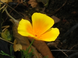 | 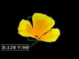 |
 | 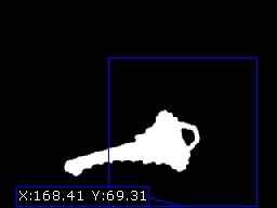 |
![]() Download the robofile used to generate the above example.
Download the robofile used to generate the above example.
Variables
COG_X - center of gravity X coordinate

COG_Y - center of gravity Y coordinate

COG_AREA - non-zero pixels within the current image

COG_BOX_SIZE - width or height of the COG box. Note that the bounding box
               is ALWAYS square

COG_WEIGHT - summation of pixels contributing to the COG

COG_DENSITY - COG_AREA / (COG_BOX_SIZE*COG_BOX_SIZE) provides a sense of how
              dense the bounding box is

COG_BOUNDING_COORDINATES - contains the 4 x,y point corners of the COG box.
COG_COUNT - specifies the number of blobs found when Individual Blobs is selected
| New Post |
| Center_of_Gravity Related Forum Posts | Last post | Posts | Views |
|
Center of gravity
Currently i'm studying the movement of the fish by using roborealm software. One of the parameter that i used in this study is c... |
9 year | 4 | 3596 |
|
is the cog height variable missing?
When I look at Set_Variables I cant seem to find a variable that tells ou the height and width of the COG box. Was th... |
9 year | 2 | 3285 |
|
Center of Gravity
I'm a student from Malaysia, currently I'm studying the behaviour of the fish by using the roborealm software. One of the parame... |
9 year | 2 | 3385 |
 Roborelam COG not appear
Hi Steven. I had problem with new installed Roborealm on my Asus PC using Windows 8.1. When I try ... |
11 year | 2 | 3846 |

Hi RR! I can identify my object with blob, using weight (image). But now I need to se... |
13 year | 10 | 4354 |

Hello. I am new to the forum and I would like to know how I can identify three centers of gravity. ... |
13 year | 6 | 4262 |
|
So far, I have been tracking one object by color. I have been using the variables COG_X and COG_Y for the coordinates of this un... |
14 year | 10 | 5071 |
 MIN_X and MIN_Y issues when calculating distance to the COG
HI, I am using roborealm to find the maximum distance of the COG of an object to either top,bottom,right or left to decide the d... |
14 year | 2 | 4135 |
|
Hey there, I recently downloaded RoboRealm 2.37, and I was trying to use the "Mouse_example1" pro... |
14 year | 5 | 4910 |

Hi, Can Roborealm assign new reference axis. For example, I have 2 objects. Object1 axis is 0,0,0... |
14 year | 12 | 7698 |

Hi, I bought the licence of the last roborealm version and I have a problem with pololu micro-maestro. | 15 year | 32 | 11530 |
|
COG
I am attempting to run the Trossen desktop movement tracking file with RoboRealm 2.32.0. I does not track but places... |
15 year | 3 | 4346 |

I want to track a shirt that I made with 3 distinct colors on it. Red, Blue, and green. You helped me with this about a year ago... |
15 year | 7 | 4699 |
|
Servo Reversing
Hi there, I just hooked up an SSC 32 servo controller board. seems to be working well. | 16 year | 5 | 5419 |
|
COG_BOX_SIZE = 0 when box display = 100%
I just noticed a bug in RR 2.14.15. If you use the COG module and set the displayed box size to 100%, then the COG_BO... |
16 year | 3 | 4641 |

Hello, I am doing a visual odometry for 3 robots with a camera (determinate the X,Y,theta - positio... |
16 year | 14 | 7984 |