
Shape Matching
The following tutorial describes one way to use a vision system to identify parts as they move along a conveyor belt. The purpose of the vision system is to identify the part and determine its location, orientation and size relative to a training model. The setup uses a DBX 21BF04-Z camera from The Imaging Source mounted vertically looking down at the belt. With the built in zoom the camera placement can be much higher than normal to allow the installation to view a larger or smaller field of view simply by changing the zoom over software.
 The camera delivers 640x480 sized images at a maximum rate of 60fps using firewire. This is much faster and bigger than is required by this
tutorial. Thus the image is scaled down to 320x240 for videos and images in this tutorial to better accommodate Internet bandwidth constraints. Note that while the
DBX 21BF04-Z provides high contrast images and a motorized zoom (which are often needed in industrial settings) you can
test the techniques described in this tutorial with a simple webcam.
The camera delivers 640x480 sized images at a maximum rate of 60fps using firewire. This is much faster and bigger than is required by this
tutorial. Thus the image is scaled down to 320x240 for videos and images in this tutorial to better accommodate Internet bandwidth constraints. Note that while the
DBX 21BF04-Z provides high contrast images and a motorized zoom (which are often needed in industrial settings) you can
test the techniques described in this tutorial with a simple webcam.
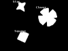
Let's first have a look at all the parts together as they appear to the camera.
Shape Matching
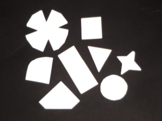
As you can see the camera has almost produced a binary or black and white image. This is desired as the purpose of this tutorial is to identify a part based on its shape. Having a black and white image will allow RoboRealm to know what pixels belong to the "part" and what pixels belong to the background (in this case our black conveyor belt).
A histogram shows the pixel intensity distribution of the above image. The graph shows the relative count of pixels of a certain intensity. In this case the intensity range is from 0 - 255 with a maximum pixel count of 320*240 or 76800. If you had a perfectly white image there would be a single line shown at the 255 (furthest right) place with a value of 76800. In most real images this will never happen and instead you will see a distribution of pixels throughout the histogram.
If you use the Histogram module to view the pixel intensity you will notice that the intensity distribution is almost binary but will still require some processing prior to shape matching. Matching shapes requires a perfect two color black and white image. The DBX 21BF04-Z makes this easy to achieve.
Image Thresholding
In order to create a binary image we use the Threshold module and set the threshold to a point at 190. Note that as the setting is manual your lighting for your parts should remain somewhat constant. Large changes in lighting will cause this segmentation to fail and parts of the background may be mistaken for foreground objects.
This is just one way of segmenting objects from the background. There are others such as the Automatic Threshold module or the Flood Fill module. These modules allow for the overall lighting to change in the image while still creating a reasonable thresholded image.
Note the difference in the image? The contrast is now 100% and the edges of the parts appear more jagged due to the thresholding, but this is what we want. The parts are all one color and ready for the shape matching module.
Before we add the Shape Matching module we need to create a database of files that contain the shapes we want to match. This is done by taking the above image and cutting the image using your favorite paint program and saving the individual shapes into each of their own files (.gif, png, ppm, etc.) within a single folder. This folder then contains 8 images one for each part. Below are the individual images used for training.


Note that the actual image sizes can be different and that only one object is shown in each image. Be sure to name the files with meaningful names as that will be the label used to identify the part.
Shape Matching
Insert the shape match into the processing pipeline and click on the train button. Specify the folder that you used earlier to save the database of images. Then click on start. RoboRealm will load in and learn the shapes in that folder. Once this is complete press Ok.
In the Shape Matching module click on the "Filename" checkbox. Now as you move your parts past the camera you will notice the filename of the part displayed in the main RoboRealm image preview alongside the object. Note that many variables are created to help you extract out needed information such as the parts Center of Gravity, Relative Size, etc. Refer to the Shape Matching module for further detail on those variables.

We have made good progress but there are still several issues we need to overcome. In the next pages we will review issues that we noticed while creating this processing loop.
Border Issues
As objects come into and out of the view of the camera their shape will not be correct. During that time the objects may be mistaken for something else.
To prevent this from creating false object detections we need to eliminate objects that are touching the border of the image. We can do this using the Blob Filter module that allows us to only select/preserve objects that avoid the border. The attribute "Location->Avoids Border" which eliminates any objects that are touching the border is added to the Blob Filter criteria. We also use this module to remove any objects smaller than 100 pixels which will help to reduce any noise objects caused by flickering lights or reflections from other moving objects.
Mirrored Parts
We also noticed that the triangle object was matching in the low 90% when moving past the camera. On further investigation we realized that the part we used in the database was a reflection of the actual part. This easily can happen when a flat object is placed upside-down without realizing so. While this would still match correctly we selected the "Mirrored Invariance" checkbox in the Shape Matching GUI dialog to better compensate for this issue.
Helpful Tips
1. What do the parts flicker sometimes?When the identification fails the part will be deleted from the current image. Thus for moments at a time a part may disappear due to a mismatch.
2. Can parts have holes?
Yes, in fact any holes in an object help by contributing to the matching process. Having consistent holes in an object can make it more unique with regard to other objects.
3. I have a mismatched part. How do I remove it using the Shape Module?
If you are matching a part with very low confidence due to the part not actually being in the database use the Confidence filter in the Shape Matching module to remove parts that have low confidence. Any part that is below 80% is probably not a good match. The default zero setting allows any confidence level which may result in incorrect matching. This can be corrected by increasing the minimum confidence value allowed.
4. How do I improve recognition?
Try to make the parts as large in the camera view as possible. The more detail in the image of the part the better the identification process can discriminate between similar objects.
If you do consistently get incorrect matches try using the filter options in the shape matching module to reduce the search space. For example, you can turn off rotational invariance which will only match objects based on the orientation of the database template file. Or you can use the size percent to eliminate really large or off-scale matches. Remember, the module is trying to match shapes at any size which can sometimes cause it to create bizarre comparisons. Telling it what to ignore can help reduce this confusion.
Be sure your objects are well segmented. Note that you NEED a black and white image in order for the shape matching to work. Your parts need to be in white and your background in black. If they are not, use the Negative module to flip black parts into white.
Be sure that your outline of the object is relatively smooth. If it isn't try using the Smooth Hull module to soften the objects outline.
Don't expect the orientation to work on symmetrical objects. A perfect circle has no orientation. Objects with one symmetrical axis such as your face can cause the orientation to flip 180 degrees at random. To get the best orientation your part will have to be asymmetrical in shape.
Videos
 (862 KB) 22 seconds video of the original images moving over the conveyor.
 (534 KB) 33 seconds video of the processed results of the parts (note that the video is slowed for viewing purposes).
Notice how the shapes will suddenly appear and disappear when approaching the border. This is the blob filter removing objects whose shape may be altered by the image borders which may cause mismatches.
Pipeline
The following is the processing pipeline as seen within RoboRealm to accomplish the part processing.
Notes:
1. You will need to train the Shape_Match module on a folder that contains the database of images to be matched. You can do this by downloading (.zip) all the images into a single folder (like c:\temp\Shape_Match), edit the Shape_Match module, press the train button, change the path to your folder (e.g. c:\temp\Shape_Match) and press start.
2. You can view the final variables (like part orientation or COG) by adding in a Watch_Variables module or selecting the appropriate checkbox in the Shape Matching module.
3. You can add in the firewire camera module or other modules to capture images. Or if you have a webcam connected just press the "Camera" button for a live feed.
Your turn ...
Want to try this yourself? Following is a zip file that contains a robofile that should launch RoboRealm with the media file that we used in this tutorial. You can click on each of the steps in the pipeline to review what the processing looks like up to that point.
Download (.zip) the Shape Matching zip file. To use this file, unzip and load the included robofile into the application. Note that the video is played back at 1/4 speed so you can view the parts going by. Also note the included folder that contains all the image files that the image is matched against.
The End
That's all folks. We hope you've enjoyed this little adventure into an application of machine vision processing. If you have any questions or comments about this tutorial please feel free to contact us.
Have a nice day!
| New Post |
| Shape Matching Related Forum Posts | Last post | Posts | Views |
|
Custom Algorithm
hello sir, I am doing research in Artificial Intelligence and robotics area. I feel glad to find RR and wish to use it in my wor... |
10 year | 9 | 4852 |
|
AVM SDK
Hi I made use of the AVM sdk simple .net in developing my academic project. Now i'm doing documentation for that project. Pleas... |
14 year | 2 | 5424 |