
Image Distortion
The ideas introduced in this tutorial have not been verified to be according to FIRST rules. Please verify with the rule manual on any modifications or unique usage of items provided in the FIRST kit of parts.
Looks can be deceiving! This tutorial focuses on the issues related to the distortion of images created from lenses that will warp and change image in ways that make measurement less precise. Several teams have realized that measurements taken from images can be very different based on what camera they are using and what focal length they believe them to be. We will try to address some of the issues here that are very common when working with image measurement from imperfect sources (i.e. webcams, Kinect, Axis cameras).
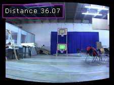
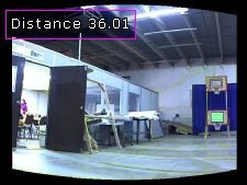
Let's first begin by identifying what issue we are referring to. Below are a couple shots taken of the Rebound Rumble target at the SAME distance but with the camera rotated from side to side. The calculated distance is shown in the upper left corner.
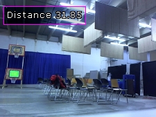
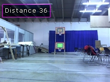
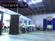
While the image target is hard to see (in green) due to the small image size what is most important is the calculated distance (this is done at 640x480). We can see that with the target at the center of the image is at 36 feet while the left and right images are at an average of 32ft. We did not move the camera forwards or backwards but just rotated it from side to side not unlike what your robot may do when turning. So where did the extra 4ft go!!
The answer has to do with what your camera lens is doing. In order to get the field of view to the size that is usable the lens will compress and distort the image in a way that is not very noticeable to us but will easily show up when measuring an object via a camera. What is happening is that towards the borders of the image more distortion is being generated that stretches the pixels a bit. This stretching is what is causing the distance measurement to think the target is closer than it is. It is not very noticeable when you look at an image using your eyes unless we compare it to a corrected image. Below is a larger view of the left side image. If you mouse over the image it will flicker between the original and corrected image. This really helps you to see the difference and get an idea of the distortion present.
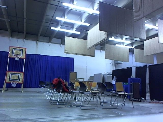
You should be able to see how the center of the image tends to balloon out with the border becoming more compressed. You should also see from the flickering that a spherical or ball like transform is being performed. The transformed image looks more like what the camera actually sees without the distortion done to better fill a square image to be presented to you. As we do not notice any issues with the original image we don't have a problem with this distortion but machine vision does!
However, you will also notice that the corrected image looks less realistic with the border parts being more distorted. While this does not look as attractive to you and I it is a more accurate image in terms of measurement.
The module we are using to correct for this distortion is the Spherical Unwarp module. This is similar to the process done before generating a 360 panoramic view as it will allow for images to be effectively stitched together (i.e. they have to be the same size in order to stitch well). Using this module just after we acquire the image from the Kinect or the Axis cameras will provide us with a more accurate image from which to measure the target distance even if the target is not dead center in the image.
Once we use this module we can then retest the above images to see how the distances have changed.

Our test images now should about error of 3 inches between the three images. This is substantially better than our missing 4ft and should be adequate information for a shooter shooting at 36ft! Due to the spherical warping module the top and bottom measurements which also exhibit the same error as left and right are also reduced (those images not shown here).
As we began the Targeting tutorial we forgot this problem and used the width of the target as the primary distance measurement. This caused the distance to drastically change as we rotated the camera from side to side. Even more than the errors we see above. Switching to using a height measurement instead helped to minimize this issue but it is still present if the camera moves up or down such as when the robot moves closer or further away from the target (which causes an up and down movement of the target in the camera image). The spherical (as apposed to cylindrical) correction allows for both horizontal and vertical correction.
This form of distortion will cause further away shots to be more incorrect in actual distance since at a far distance each pixel really counts towards the distance. At a close range this error is still present but reduced. Thus if you plan to shoot very close to the target this distortion may not be as much of an issue.
For those of you using the incremental targeting technique (i.e. you have the camera attached to the turret) this process *may* also not be as necessary. This is because the assumption will be that you only fire when the turret and camera see the target in the center of the image which has the most square view from anywhere in the image and will likely return a reasonable distance value. If you are using the camera to calculate distance of the target from a non-centered image you WILL need to add this module into your pipeline and calibrate it accordingly. Otherwise you may be off in distance by a couple feet!
Even in case where measurement is not as necessary correcting the image can make the processing much more stable. For example, in our Ball Recognition tutorial we noticed that in one image the ball appears more like an ellipse. Using the spherical module helps to correct that back into a circle.
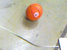
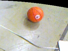
In this case the corrected image's shape actually works to create a stronger circle detection for the ball.
To try this out yourself:
- Download RoboRealm
- Install and Run RoboRealm
- Load and Run the target recognition module
 robofile which will show the target
distance. Use 3 images as we have above of the center, left and right and use the
GUI interface to increase the curvature and offsets till the distances are as close as possible
to each other.
robofile which will show the target
distance. Use 3 images as we have above of the center, left and right and use the
GUI interface to increase the curvature and offsets till the distances are as close as possible
to each other.
- Note that you probably want to save 3 images from your camera and drag them into RoboRealm to test. If you use live images too much noise will be in the images for you to do accurate comparisons.
If you have any problems and can't figure things out, let us know and post it
in the forum.