
Visual Targeting
The ideas introduced in this tutorial have not been verified to be according to FIRST rules. Please verify with the rule manual on any modifications or unique usage of items provided in the FIRST kit of parts.
This tutorial assumes that you have acquired an image of some form and need to process it to determine the distance from the camera to the target. This information would be used to determine the speed of the shooter in order to effectively range the shooter for the appropriate distance.
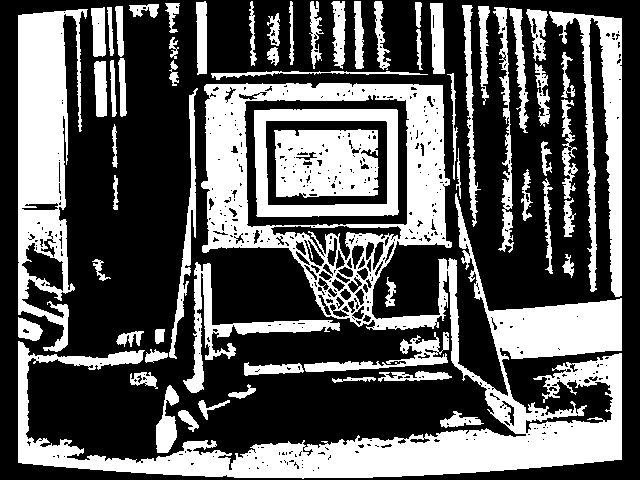
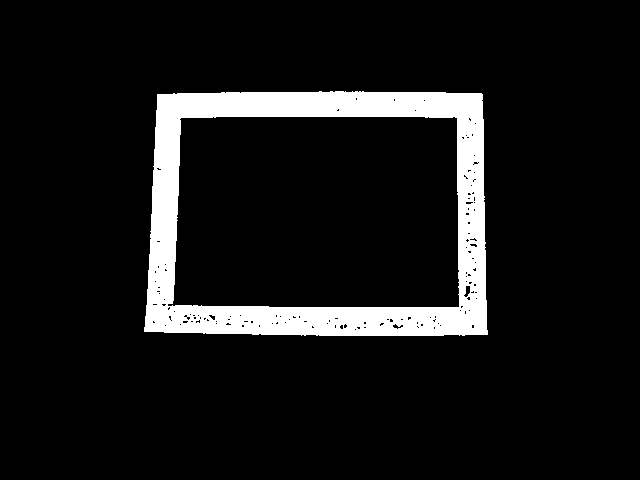
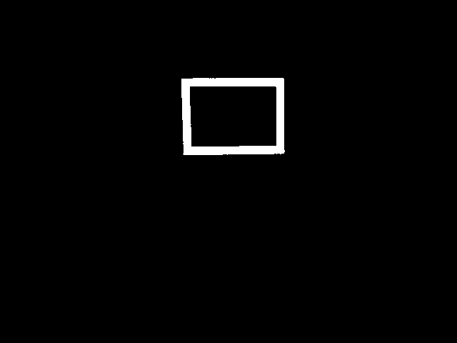
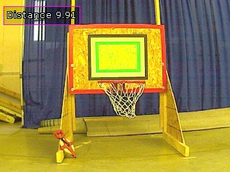
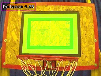
Let's assume the following two images are to be processed. They show the target at different distances since the techniques used are meant to scale to different sizes so that we can range near and far targets.
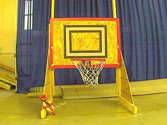
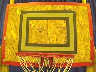
Note that we have purposely not used the IR image nor used the true nature of the retro-reflective tape to eliminate most of the image prior to processing. Either of those images will also work with the following technique, albeit with more stability since there will be less interference from surrounding objects. Thus this technique will work on any type of image.
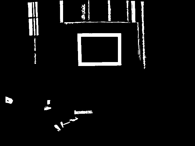
The first thing we want to process for is the light and dark relationship between the border of the reto-reflective tape and the black tape around it. By separating the rectangle from the rest of the image we can proceed to isolate and extract just that object. First we use the Adaptive Threshold module to convert it into a black and white image.
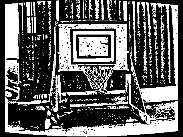
We can see that using that module extracts the white square quite nicely. Next we use the Blob Filter to remove objects smaller than 100 pixels because they are probably not targets.

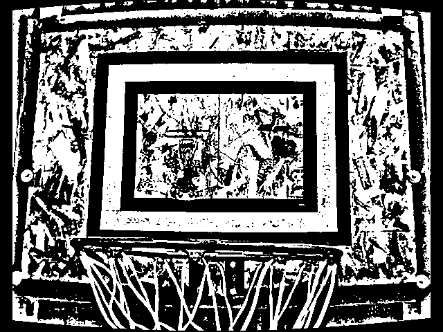
Then we continue by eliminating blobs (connected pixels) that do not adhere to the perimeter generated by a 4 sided rectangle (or quadrilateral). This ensures that the blob has 4 relatively straight sides.
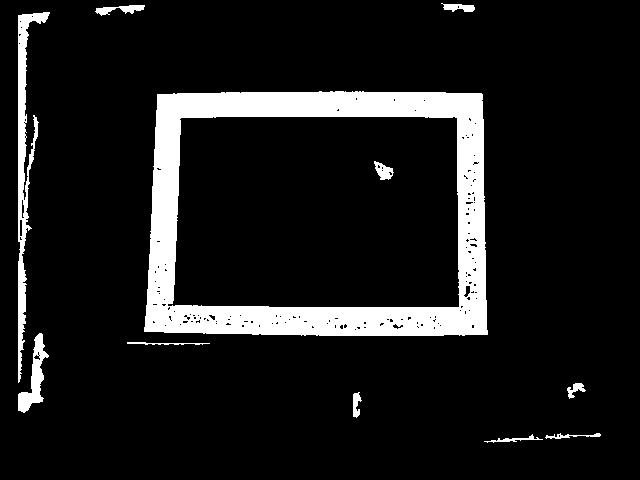
We can see that we are getting closer but there are still a couple blobs that also have squarish sides. So we continue with the blob filter and measure the lengths of the quadrilateral sides. They should ideally group into two similar sizes (left, right and top, bottom) to be a well formed quadrilateral. Using the ratio of these sides we can eliminate objects that are not well formed.
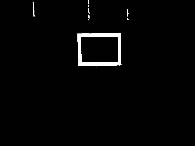
Finally we use the property of the target itself in that it is a thin ribbon around a larger area. By using the ratio of the area formed by the 2" tape with that of the entire size of the target (i.e. its bounding box) we get a very low white area to total area ratio (i.e. the object is not very dense). This area / bounding box area ratio helps to eliminate the final unwanted blobs.

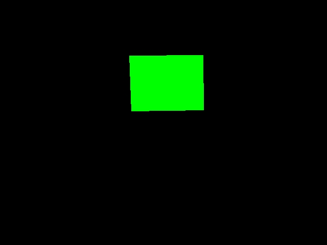
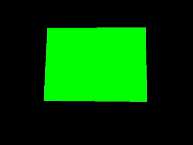
Now that we have the target isolated we need to understand what the actual dimensions of the target is. To do this we fill the hole in the target (which was useful as a density measurement in the previous stage) and replace the remaining rectangle with a best fit rectangle using the Blob Replace module.
This module generates 4 coordinates per blob (8 points total) that we can use to perform calculations on. We use the following VBScript code to determine the size of the vertical center line. We use the vertical center line (instead of the horizontal) since the vertical center line of each square is not as susceptible to a side view as a horizontal line is. When you move to either side of the target perspective will warp the horizontal line more than the vertical assuming the target is still somewhat in the center of the image.
list = GetArrayVariable("BFR_COORDINATES")
if isArray(list) then
  if ubound(list) > 0 then

    targetPixelHeight = 0
    targetSamples = 0

    ' calibrated for an Axis camera
    imageHeight = GetVariable("IMAGE_HEIGHT")
    cameraFieldOfView = 47.5
    targetHeight = 18.0

    for i = 0 to ubound(list) step 8
      ' grab list of coordinates from blob_replace
      ' note the array is sorted by previous module in a specific order
      righty = list(i+1)
      rightyy = list(i+7)
      lefty = list(i+3)
      leftyy = list(i+5)

      ' based on these two side lines get the center line height
      ' the center line is used since we want to aim to the center
      ' of the target. This also removes any perspective distortion
      ' where the right or left size may be a couple inches closer
      ' or further away from the camera
      targetPixelHeight = targetPixelHeight + _
        ((lefty - leftyy) + (righty - rightyy)) / 2

      targetSamples = targetSamples + 1

    next

    targetPixelHeight = targetPixelHeight / targetSamples

    ' we can use a known distance to determine FOV if we don't know it
    ' measuredDistance = 10.0*12.0
    ' write "Calculated FOV " & _
       (((atan((((targetHeight*imageHeight)/targetPixelHeight)/2)_
       /measuredDistance)*2.0)*180.0)/3.14159) & vbCRLF

    ' determine distance in inches
    totalDistance = (((targetHeight*imageHeight)/targetPixelHeight)/2)/_
      tan(((cameraFieldOfView*3.14159)/180.0)/2.0)

    SetVariable "Distance", CInt((totalDistance*100)/12)/100

  end if
end if
Using this code result in the Distance variable we then integrate the results back into the original image and show the results. The code above uses all detected targets to create a more precise number than just using one individual target. We now have a variable that represents the distance from the camera to the target.
To try this out yourself:
- Download RoboRealm
- Install and Run RoboRealm
- Load and Run the following
 robofile which should produce the above results. If you are using a Kinect with the IR camera
download this robofile which will relax some of the shape requirements.
robofile which should produce the above results. If you are using a Kinect with the IR camera
download this robofile which will relax some of the shape requirements.
- You may need to configure the cameraFieldOfView depending on which camera you are using. You can also change that number slightly to help improve the accuracy of your results.
Be sure to also review the FIRST Vision Targets White Paper if you have not already seen that document.
If you have any problems with your images and can't figure things out, let us know and post it
in the forum.