

Target Localization
The Target Localization module provides detection of a specified target to calculate the position of the camera/robot based on the orientation and size of the target. In order for the target to be accurately detected a couple assumptions are made.1. The target is composed of horizontal and vertical lines. Some curved edges are acceptable but the majority of the target is composed of straight lines.
2. The target's edges are sharp and of high contrast with respect to the rest of the image.
3. The target is perpendicular to the plane of movement. I.e. the camera/robot moves on the ground/horizontal plane in front of the target. While some tilt and roll is permitted, significant tilt or roll will cause detection failure. It is assume that your camera/robot stays right side up.
4. Most of the target is in view. Some obstructions are permitted but enough corners must be visible for detection to work.
5. The target is planar, i.e. it must be on a flat surface. If the target is bent or curved in any way detection will fail.
Given these assumptions the module will return with X and Y coordinates of the camera relative to the target such that you can know your approximate location.
The module has no specific units specified (i.e. meters, feet, etc.). The results will be in whatever units you use for the size of the target. Thus, if you use feet for the size, the X and Y results will be in feet. If meters are used, the results will be in meters.
Target Image
 The target image specifies what pattern to detect. The white area represents the target whose outline consists of
straight lines. These edges will be detected within the current image. The black areas represent the background
of the target where no edges are expected to be present. This is used to provide detection context within a cluttered
scene. The gray areas represent areas that can be disregarded since they are unknown and can change depending on the
background scene.
The target image specifies what pattern to detect. The white area represents the target whose outline consists of
straight lines. These edges will be detected within the current image. The black areas represent the background
of the target where no edges are expected to be present. This is used to provide detection context within a cluttered
scene. The gray areas represent areas that can be disregarded since they are unknown and can change depending on the
background scene.
The intensity levels of the image are very important. If the target is not perfectly white (255,255,255), the black area not perfectly black (0,0,0) and the gray area not (128,128,128) the template will be incorrectly interpreted and fail. For this reason, only lossless image files (GIF, PNG, PPM, TIFF) are accepted as template files. The use of lossy formats (JPG) would cause the intensity to change.
Hotspots
Once the target is detected, you may need to know the position of points within the target. To do so, you can specify hotspots. There are 5 hotspots that you can define. They are represented by a + pattern within the template in unique colors. The 5 permitted colors are Blue (0,0,255), Green (0,255,0), Cyan (0,255,255), Red (255,0,0), Purple (255,255,0) and Yellow (255,0,255). In order for detection of hotspots to work, they MUST be in a + formation
[ ] [*] [ ]
[*] [*] [*]
[ ] [*] [ ]
and be the EXACT color. Failure in the pattern or color will stop the hotspot from being recognized and position provided. For all hotspots, the distance, horizontal and vertical angles are reported based on the color of the hotspot, i.e. the variable name will include the color (red, blue, etc.) of the hotspot.
Map
You can specify a additional image that provides context for the X and Y coordinates. This background image can help to visually identify where you are with respect to the target. This is a pixel based image that can be any image format loaded by RoboRealm. The dimensions of the are important. Depending on what units you use for the target size, a pixel within that image will represent a square unit of that dimension. For example, if you specify the target size in inches, each pixel within the map image represents a square inch in real space. Keep in mind that position 0,0 is right in the middle of the target (which is an unrealistic point since you'd not be able to see the target and therefore not know where the camera is). The map may be larger than this space which requires the use of the map target X and Y points to adjust to this location.
Interface
Instructions
1. Target Template - Specifies the filename of the target image.
2. Physical Target - Specify the actual size of the target in whatever units are most convenient.
3. Camera Properties Field of View - Specifies how many degrees the camera can see/image. The larger the field of view the more context a camera can see.
4. Camera Properties Focal Length - The focal length determines the amount of perspective distortion that occurs when looking at the target from the side. Check with your camera vendor for the focal length or use a side view of the target and change the focal length until you get a good match.
5. Target Appearance - Specify how the detected target should be identified in the current image.
6. Target Match Threshold - Specify how well the match should be in order to be detected.
7. Max Dist Change - Specify the maximum distance the robot can move in a short period of time. This value is used to ignore sudden incorrect detections of the target which can dramatically move the position very quickly.
8. Use Feature Type - Specify which feature type should be used. The target localization module looks for corners in order to determine the mapping between actual and template. Sometimes, the outer (convex) corner is more reliable than the inner (concave) corner depending on the target used. Typically corners that are created within the target as apposed to on the border of the target are more reliably detected since the background may change.
9. Show Features - This checkbox will help indicate the detected corners.
10. Map Options Image - The bitmap of the background map.
11. Map Target X/Y - The offset within the map that defines the 0,0 point (i.e. middle of target).
12. Robot & Route Color - The respective color of the robot and taken route.
13. Map View - The robot position on top of the bitmap map.
14. Center on Robot - Specifies that the map should center on the robot location. When this is unchecked you can scroll the map area by dragging it with the mouse to view other positions.
15. Smoothing Size - The raw number of the X and Y position of the target can be very noisy (sporadic) if not smoothed with previous values. The more smoothing applied the more stable the position is. However, with more smoothing comes slower updates in that the reported position will lag a little behind reality.
Examples
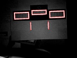 | 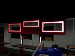 |
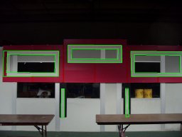 |  |
Variables
TL_MATCH_SCORE - The match score of the detected target
TL_X_TRANLATION - The number of pixels the target is off from horizontal center of screen
TL_Y_TRANLATION - The number of pixels the target is off from vertical center of screen
TL_SCALE - The scale of the target relative to the template
TL_X_ROTATION - The amount of tilt rotation the target is relative to the camera view (up or
	down of target)
TL_Y_ROTATION - The amount of pan rotation the target is relative to the camera view (left
	or right of target)
TL_Z_ROTATION - The amount of in plane rotation of the target
TL_TARGET_DISTANCE - The distance of the center of the target from the camera
TL_ROBOT_X - The X coordinate of the camera relative to the target
TL_ROBOT_Y - The Y coordinate of the camera relative to the target
See Also
Fiducials
Shape Match
| New Post |
| Target_Localization Related Forum Posts | Last post | Posts | Views |
|
Is the following possible, using the RoboRealm software?
Hello! My name is Roi. I have this 40cm long RC plane, that flies in front of a very ... |
12 year | 2 | 3297 |
|
How to output only one blob in blob_filter?
How can we output only the highest-scoring blob based on blob_filter's aspect filter?... |
13 year | 4 | 3828 |