
Sparkfun SerIO
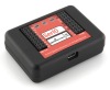
The Sparkfun SerIO module provides an interface to the SerIO (Serial Input/Output board) sold by Sparkfun. This board has a USB to serial connection with a PC and can operate at 57600 baud which makes it an ideal platform for communication with a PC. The SerIO has 6 PWM/Analog Out (Servo) capable digital signals, 8 analog in and 14 digital IO lines (shared with the 6 used for PWM). Thus, you can use this inexpensive board as a servo controller and an analog/digital IO board for your robotic projects.The SerIO is based on the Arduino platform (thus the pin similarity). The SerIO is beneficial over the Arduino in those cases where you prefer not to be responsible for programming an Arduino to provide servo and IO capabilities. If programming is your thing you'll probably be better off with the Arduino. However, if you intend to move to custom control of the Arduino at a later date and need something to get up and running without much difficulty the SerIO offers a very nice solution in this regard.
The 6 PWM lines are part of the 14 digital IO lines. If you need to control 6 servos then you will have 6 less digital IO lines.
Interface
Instructions
1. COM Port - Specify the COM port that your SerIO is connected to. Note that the SerIO comes with a USB cable that simulates a serial port on your PC. The port number for these kinds of virtual ports are normally above the standard 1-4 physical ports.
2. Remember As Default - Select the "Remember as Default" checkbox if you would like the current COM setting to be remembered by RoboRealm such that whenever the SerIO module is loaded the COM port will be auto-populated to the current setting. This ability allows you to not have to constantly change the COM port setting when loading in successive RoboRealm robofile configurations.
3. Servos - Once communications are specified and you have a servo hooked up to the board you should be able to move the appropriate slider according to which pin you used in order to see the servo move. If the servo does not move, check your servo connection and that the COM port/USB cable are all connected and properly specified.
5. Variables - Select the appropriate variables that contain or will contain the position value that will be sent to the servo board. This is used to automatically change the servo values based on your VBScript (using the SetVariable function) or Plugin based program.
6. Current Value - To manually set the servo position type in the appropriate number (0-255, 128 is the default neutral) into the text area or use the slider to adjust the value. The servo position will be updated as appropriate. Note that the current limits of 0 and 255 will most likely be beyond the capabilities of your servos so you may want to tighten the range.
7. Sliders - You should be able to move your servos by dragging the sliders to the right or left or by specifying a number within the current value text box. If the servos do not move check your USB cable and/or servo connections.
8. Min/Max Limits - You can also use the min/max limits to ensure that even if the variables specify large or low values (due to programming errors) that the board does not actually attempt to move the servos above or below the specified limits. This can be used as an additional precaution in case your servos cannot physically move beyond certain limits.
9 Analog - If you want to sample the analog values specify a variable or type one in that will contain the value from the appropriate pin. Note that you must select the checkbox next to the Analog Pin in order to activate this functionality. As soon as the pin is activated the value read at that pin will be displayed. Note that even when unattached the pin will show a very low value due to noise. Also note that when pin 0 goes high that other ungrounded pins will also go high due to signal bleed.
Once the value is placed within the variable you can then use this value in other modules, or accessed via the API, extension, etc. in order to move the value outside of the RoboRealm application.
10. Digital Pins - The SerIO comes with 14 digital IO pins that can be configured as an input or an output. Unlike Analog pins, Digital pins can only receive a 1 or 0 (on or off) as apposed to a full numeric 0-255 value. Likewise, a digital pin set to an output can only send an on or off to the pin similar to a switch.
Each pin can either be set as an input or output. Do this by selecting the "in" or "out" radio button next to each pin. If you are specifying a pin as an output selecting the checkbox will then turn that pin high or low. Be sure the enable the pin (first checkbox) to enable the controls for that pin. Again, if you enable pin 3,5,6,9,10,11 a Servo configuration in the first tab will be disabled. These pins are marked with a '*' in the Digital tab.
For input pins the checkbox will reflect the read high or low state of the pin but will remain disabled.
To automatically send or receive a bit select or type in a variable that will be set if the pin is configured as an input or read into if the pin is configured as an input. Note that you can tell RoboRealm which bit of the variable you want to set/get by using the provided bit dropdown.
As an experiment, you can connect an LED to pin 2 and then select the pin as an "out", By checking and un-checking the checkbox you can make the LED blink. Alternatively, if you don't have an LED handy try this on pin 13 as that is connected to the LED next to the Tx and Rx leds on the SerIO.
If you then select the IMAGE_COUNT variable (which holds the current image counter) as the variable and select Bit 0 the LED will blink for every two frames captured. Selecting successively higher bits will slow the blinking by a factor of 2 for every bit.
See Also
Sparkfun Arduino
Axon
Parallax BoeBot
For more information
Sparkfun SerIO
| New Post |
| Sparkfun_SerIO Related Forum Posts | Last post | Posts | Views |
| None |