
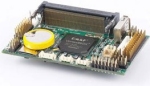
DMP RoBoard
The RoBoard module provides an interface to the intrinsic control capabilities of the RoBoard nano sized PC based computer board. This miniature computer can run RoboRealm (assuming WinXP is installed) and provides a shared 24 PWM servo or digital IO pins and 8 analog in pins (not to mention the ability to attach a USB webcam!). This PC was built for embedded robotics and offers a great solution for onboard processing with RoboRealm.The RoboRealm module provides easier access to the boards capabilities by exposing the pin configuration in an easy to use GUI format that is run right on the board itself. The module allows for vision processing to directly affect the robots motors, servors, etc.
Note that the module will show on other computers than the RoBoard but will of course not reflect the correct values nor move any servos!
Depending on your installation you will need the Microsoft VC8.0 redistribution files in order for the RoBoIO.dll to run (this DLL provided by RoBoard). You can download these zipped files here. Download and unzip directly into the RoboRealm folder if you find that the RoBoard module does not move any servos when it should.
Interface
Instructions
1. Servos - Select the appropriate tab that indicates the range of servos that you want to work with. Then test the servo out by using the slider to change the servo position or use the text box/spin buttons to change the values with more precision. Moving the slider or changing the current value should move the servo. If it does not then check the pin number and the servo condition.
To automate the movement of the servo you can select or type in the name of a variable that contains the position value to be sent to the servo. This variable can be created by other modules or set by external applications via the API. Note that the slider and value fields are disabled when a variable is selected to indicate that the servo is now under automatic control and cannot be manually set. Removing the variable will again allow manual changes.
If you find that the servo drifts even at 1500 (neutral) then change the trim to stabilize the servo. In this way your application can still consider 1500 to be neutral without needing to change the number.
To protect your servos from damage you can change the Min and Max limits which will prevent values beyond the specified range from being sent to the servo incorrectly. This can also be used to limit the range of the servo if it physically cannot move within its full range.
Note that a Servo control will be disabled if the Pin is instead used as a General Purpose Digital Input/Output pin instead (GPDIO).
2. Analog Input - The analog input tab shows the current values as registered by the Analog input pins. The value will range from 0 to 1024 (10 bit value). To react to these values type in or select a variable that will be assigned the current value present at the pin. Note that 5V produces a maximum value of 1024.
3. Digital Input/Output - Select the mode that you want to assign to the particular pin. All pins are by default set as Servo pins. By changing the mode you can instead use the pin as a digital input or digital output.
When you select the DOUT (Digital Output) mode the variable and checkbox become enabled with the mirrored Servo control being disabled (i.e. the servo control at the same pin). By clicking on the checkbox you can set/unset the pin value. By attaching an LED to the appropriate pin you should be able to manually switch on and off the LED. Note that DOUT produces an approximate 3V out so most LED's should handle that easily.
Selecting a variable will then disable the checkbox to indicate that the DOUT pin is under variable control. The variable needs to contain either a non-zero value for the pin to be set high OR if the BIT field is selected then the specified bit in the variable will need to be set for the pin to be set high. For example, if the bit is set to 2 then the variable will have to contain 4 to 7 for the bit to be set high (i.e. bit number 2 or the 3rd binary bit needs to be set).
Selecting DIN (Digital Input) will allow you to type in a variable that will contain a 1 when the pin is drawn low. By default the pin will be 1 when the pin is not connected and a 0 when connected. If you wish to instead set a bit within the variable select the appropriate bit number in the dropdown box. The bit selection allows you to construct a single binary number from multiple DIN fields. To do this use the same variable name in multiple input fields with increasing bit numbers.
4. Stop - Press the stop button to center all servos and prevent any variable values from being sent to the servos. Note that this does NOT disable the DIN, DOUT or Analog in tabs.
Notes
1. It is worth mentioning a couple tricks when working with the RoBoard. First, you will need the VGA card for the initial installation of the operating system, but after this you can remove the card and just use Remote Desktop to connect to the board. This just requires an Ethernet card (or wireless communication) in order to work with the RoBoard. Note that applications like VNC require the card to remain inserted as they are screen scrapers of which Remote Desktop is NOT. To enable Remote Desktop right click on the My Computer icon, select the Remote tab and check the "Allow uses to connect remotely ...".
2. Be VERY careful when changing values for the min/max for the servos. It is possible to change the values and send a very low or high value to the servos. The RoBoard is capable of sending a position value of 1 (much less than the 500 boundary) which can ruin a servo (this based on experience!).
3. The black or negative PWM wire is of the outside side of the board with the signal (white or yellow) being towards the middle.
4. As the RoBoard is a regular PC all the other modules within RoboRealm such as the Play Wave File and Speech Recognition will work with the appropriate attachment of speakers, mic, etc.
5. As apposed to just turning the RoBoard off use the Windows Start button->Run and type in 'shutdown -t 1' which will cause the board to shutdown normally.
6. The RoBoard is currently (March 8th, 2010) the SMALLEST PC based board that we are aware of but along with that comes some performance issues. It is recommended that you use as small an image as possible (80x60 or 160x120) as the USB speed of the board is not like that of your laptop or desktop. Keeping the image small will allow a capture rate of about 15fps with the appropriate lighting. In our tests an image size of 320x240 slows this down to about 10fps.
For more information
RoBoard Website
| New Post |
| DMP_RoBoard Related Forum Posts | Last post | Posts | Views |
|
Roboard module servos not moving
Hey, I checked the forum and googled around and I couldn't find any solution to my problem. The sliders on the DMP_RoBoard modu... |
15 year | 6 | 4933 |
|
about using the roboard
it has 1ghz processor and 256mg of ram and you said roborealm needs 2ghz 64mb ram min Memory - 64Meg... |
15 year | 5 | 4968 |
|
Low FPS on Roboard
Hello, I am having a problem with rather slow frame rate at only 4-7 FPS. I am running Windows XP on a Roboard-110... |
15 year | 2 | 4724 |