|
Distance and size measuring help?
Mark [7 posts] |
19 year
|
Fantastic program! After only a short time playing with it, most of it made sense.
What I would like to do is be able to measure distance in pixels between edges. Take for instance the line following turorial on this site. We can find the center of gravity for the tape, but what if one wanted to measure the width of the tape? Is there a simplistic way to do that? Of course with the tape always changing direction in the field of view it would be difficult. But if the tape was always presented as running from the top to the bottom of the screen and only its width varied, could it be measure?
Once the edges were enhanced with filtering, I would think one would have to start at the left side of the screen, look at each pixel in one row (say the middle row of pixels) and find the transition from dark to light. That pixel would represent the LEFT EDGE of the tape). Then do the same from the right side on the same row of pixels (RIGHT EDGE). Once the two points were found the distance could be calculated.
The trouble is, I'm not sure how to use the software to look at each pixel in a row of pixel, and I'm not even sure if this is the best approach.
Any hints?
Thanks!
|
|
|
|
Mini Distance Tutorial
Anonymous |
19 year
|
There are many ways to do this one ... here is one example.
Lets start with the original image

Apply adaptive thresholding with a wide window to narrow in on the line to get

then flip to negative so we have white blobs, remove small blobs and fill any black holes that can be filled

Now that we have a nice clean line lets get its border

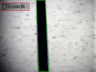
and then clip most of the image away to just find the center line

from here we add the blob filter which creates an array of all the COG's of any blobs left in the image. Add a little VBScript to calculate the distance between two blobs and the variable display routine overlapped with the original image we get

Few ... almost ran out of images! But we made it!
Some quick variants to this would be to use more VBScript after the border routine to sample the pixels directly from the image. Have a look at the VBScript docs at http://www.roborealm.com/help/VBScript_Program.php (lower part of the page) as to how to do that ... there are probably 100's of other ways too.
Try it yourself with the include robo-file below...
STeven.
 program.robo program.robo
|
|
|
|
And another ....
Anonymous |
19 year
|
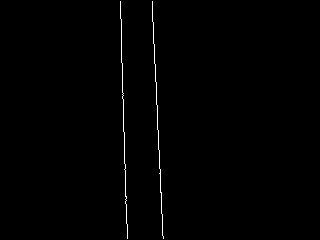
To eliminate much of the first couple of steps you can use an Edge detector (like in the tutorial) such as canny. The first step with the canny edge detector then looks like

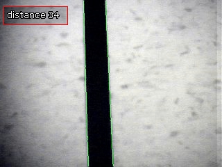
with the final one looking like

note that the detected lines match better with the edges of the black line and also come out with a different answer 34 instead of 31 ... just goes to show you how using different techniques will result in different answers.
STeven.
program.robo
|
|
|
|
Wow! That works very well.
Mark [7 posts] |
19 year
|
Very nicely done. Thank you so much for the sample program. It helps so much to be able to step through it and see how each of the functions behaves on the image. And, I didn’t think that vbs could be used to grab pixels. At first I thought it would open up even more possibilities, but the section on vbs warned of performance issues.
It would seem that “blob thinking” VS pattern searching seems to be one of the keys to success.
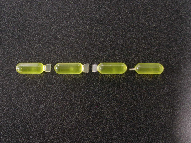
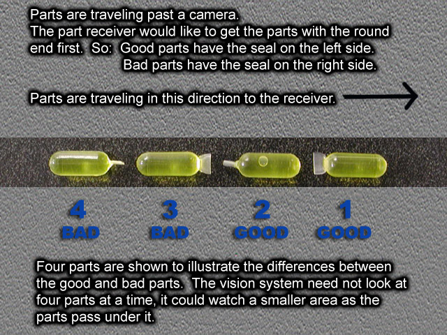
For instance, I put up a pic of some yellow liquid filled tubes. If I wanted to find a tube with the crimped seal to the left, would “blob thinking” work? Is there a particular method of finding a yellow blob with a white blob touching its left side?
I’m going to run through all of the program’s tools and see if I can figure it out, but if you could nudge me (and you can’t nudge too hard) in the right direction, I would be grateful.
Thank you!
Mark

|
|
|
|
1st guess...
Mark [7 posts] |
19 year
|
I haven't tried anything with the program yet, just reading through the documentation. Here's a guess at a plan of attack to tell which way a tube is facing - find the COG of the part. Docs say that the brighter pixels (the crimp?) will weigh more and pull the COG towards them. Knowing the COG position in relation to the bounding box (of which I yet have no idea how to calculate) of the tube blob, I should be able to tell which end the crimp in on. Does that sound remotely plausible?
Thanks!
|
|
|
|
Quality Assurance
Anonymous |
19 year
|
Mark,
Yes, the COG versus boundary box would be one way to go ... the crimped end would be smaller and thus not effect the COG as much. But here is another way ..
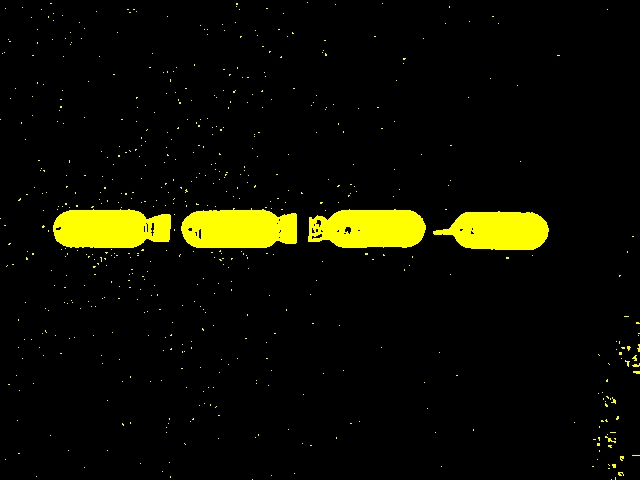
Lets first segment the image based on the color yellow

and then remove all smaller blobs that are just noise

which could even be configured to remove the crimped tablet since it is smaller in size than the others. But this would require a stable setup with a known distance from camera to table. Instead we continue to fill in any holes to get solid blobs

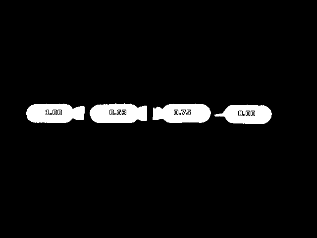
then we use the bitmap comparison ability in the blob filter and select the first blob as the template. This results in a shape similarity measure which results in weight that look like

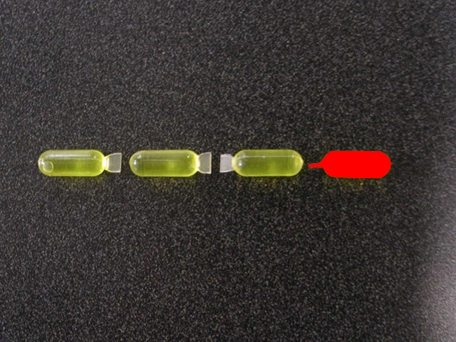
which one can easlily notice that the rightmost object is not like the shape of the other. We threshold at 0.5 and invert the selection to just select the bad object. Using this and colorizing, etc we get the final image as

which identifies the bad tablet in red.
Note that the bitmap template used is

and that using this comparison will ignore size and orientation making the detector much more reliable than just using the object area.
Is that enough of a nudge?
We would also like to ask that we can use the image in a tutorial that will show off the bitmap blob filter since the image you provided works so well with that system.
Note that to run the robo-file you will need to respecify the bitmap shape file.
Thanks!
STeven.
program.robo
|
|
|
|
One more item
Anonymous |
19 year
|
You'll need to redownload RR as we just added the colorize routine in since we've need that module for the last two posts anyhow.
STeven.
|
|
|
|
Bitmap comparison… this could be fun..
Mark [7 posts] |
19 year
|
Hi Steven,
Yes, that was a very good nudge. And yes, please use the submitted pictures for whatever you like. I’d be happy to submit any others that you need.
And now on to my apology for being ambiguous with the description of what I was trying to detect with the tubes. I have the advantage of being familiar with them, and invariably instructions are sometimes written by someone who already knows what he is doing, thereby leaving all the important stuff out.
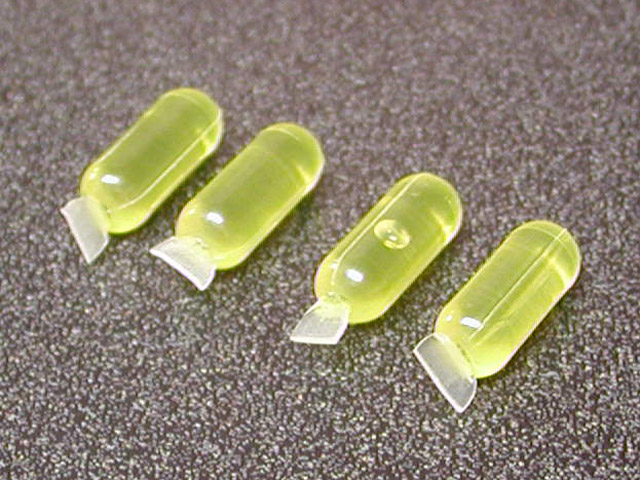
The tube that you detected does look like it has the smallest seal, and could be seen as the defective one. If I hadn’t taken the pictures, I would have thought so too. In fact, it was one of the good ones. It just had its seal rotated so that the thin face was pointed to the camera. I’ve attached a picture of the ends of the tubes to illustrate.

I’ve also attached a picture showing which ones are bad VS which ones are good as determined by which way the seal is positioned in relation to the tubes’ travel direction.

I did try COG but as you said, the seal is too small. The COG comes out the same for every tube.
So, I wonder if the best way would be bitmap comparison with the SHAPE_ORIENTATION variable to determine if the seal was leading or trailing. I haven’t tried it yet, but it looks like several images can be used for matching, which I would need, as the seal can appear thin or thick depending on rotation of the tube along the axis of its cylindrical body.
Sound thinking, or is there a better way?
Thanks!
Mark
|
|
|
|
Circles
Anonymous |
19 year
|
Mark,
Yes, that would be the way to go ... you could use perhaps 4 or 5 images to best capture the rotation of the part and then filter against its orientation. We'll actually try that out to see if it works since I'm not sure the orientation is currently exposed to VBScript.
In the meantime, we found another rather interesting approach that uses one of our new features that we just launched. It is strange in that we ignore the seal side of the tablet and just focus on the other end. It always seems to be a nice semi-circle. Thus using the circle detector and a little VBScript comparison we can deduce the orientation of the part ... here's how.
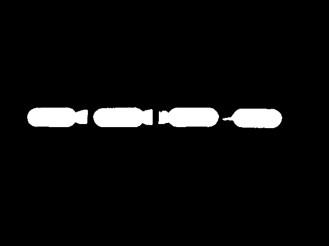
We start with the original image above and use the same yellow filter and fill routine. We then use the Blob filter to eliminate small particles and also build the blob array which contains the COG of all the blobs to get

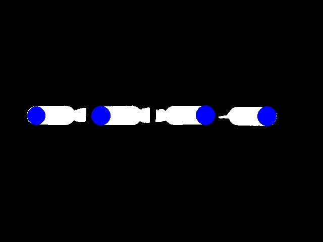
Which we then feed into the circle detector to get

You can probably see where we are going with this now ... since we have the blob array with the COG and the circle array with the circle centers we can then compare the blob cog and the circle cog to see which side of each the other is on. One side is good, the other side is bad.
The following VBScript does this ...
circles = GetArrayVariable("CIRCLES")
blobs = GetArrayVariable("BLOBS")
result = "-- "
if isArray(circles) then
if ubound(circles) >=1 then
j = 0
for i = 0 to ubound(circles)-1 step 13
if circles(i) < blobs(j) then
result = result & "BAD "
else
result = result & "GOOD "
end if
j = j + 2
next
end if
end if
SetVariable "result", result
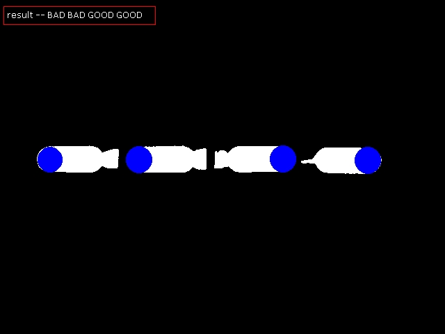
It basically steps through the two arrays (note that one has 13 entries whereas the other has 2 thus the use of i and j iterators). Based on the
X coordinate of the circle versus the blob we determine good or bad. The final result would look like

This one is nice since it does not require any bitmap templates (so it is more general) and will always look for the side that is nice and round which is the main point of the system anyhow. Goes to show you that understanding the larger problem can sometimes lead to simpler solutions. The seal side of things is quite dynamic and somewhat diluted in color so it is harder to detect ... but the other side is nicely stable and nicely shaped.
We actually have a couple more ideas to try ... but that is for another posting.
STeven.
program.robo
|
|
|
|
Yes!
Mark [7 posts] |
19 year
|
Ooooo.. that’s good! Oddly enough I had to turn down the max radius on the circle tool from 100 to 95 to get the program to see the far right tube end on my computer. Don’t know why, but at least I understand more from playing with the settings to make it to work as you did.
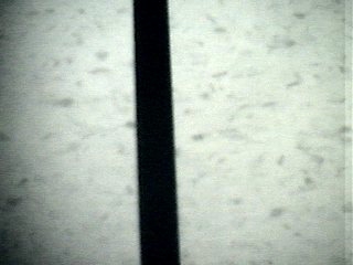
Ah.. yes the orientation variable on the blob bitmap filter isn’t exposed to vbs. I had been looking at the shape matching tool which does. So I gave it a try to see what I could do with it. I started with the base picture.
[image1]
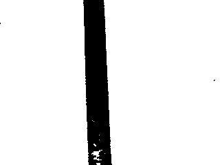
Filtered it out to 4 blobs.
[image2]
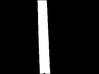
Used a 1 bit binary matching image.
[image3]
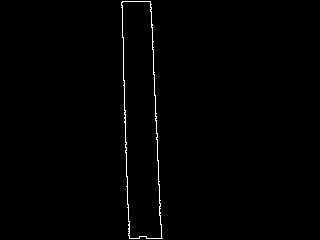
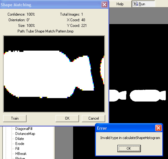
Placed the image in a folder all by itself and pointed the shape tool to the folder it was in.
And I ended up with this error.
[image4]
I tried using a gif, and a bmp. I tried saving them as 1 bit binaries and then tried RGB. Got the same errors.
The shape interface skewed the image in its widow as you can see from the error picture, though the degree of skew was different depending if I used a gif or a bmp.
Am I using this feature correctly?
I attached the program.
Thanks!
Mark
p.s. Should I have started a new post for easier reference on the forum index? I don't know if the shape matching tool qualifies as a separate subject.
program.robo
|
|
|
|
Pics for previous post...
Mark [7 posts] |
19 year
|
The forum won't take bmp's... and I had one in there. So it left all the pics out. Here they are, with the bmp changed to a gif. Yeah!


program.robo
|
|
|
|
Anonymous |
19 year
|
Hi Mark,
Yes you are using it correctly. There were a couple issues in that module that have now been fixed and a bunch more capabilities have been added.
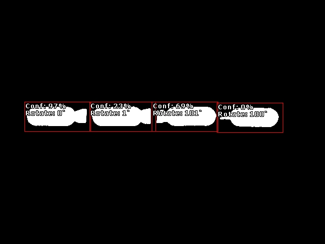
Download RR again and you should have a nice solution to your project. You can now filter on the orientation of a match within that module directly. Interesting in that even though the crimped seal tablet did not match very well shape wise it still determined the correct orientation regardless ... thus you can nicely filter the image for those tablets that are the wrong way round using just one template.
You would just filter any orientation in the range 170 to 190 degrees which would eliminate all tablets not in the right orientation. Or if you wanted to cause some machine to brush away the bad ones you would instead detect from 350 to 10 degrees which would eliminate the good ones from the image and allow the robot to target any remaining bad tablets.
Give it a try and let me know how it goes. I've attached an image of what the final analysis looks like in that module so you know what to aim for.

STeven.
program.robo
|
|
|
|
Wow!
Anonymous |
19 year
|
Oh my gawd! That is exactly the tool I'm looking for. For those of you just tuning in it works wonderfully now. ( I see someone else in another post was also trying this tool). The displays, for confidence, location, orientation, etc. are so helpful. Not to mention, the docs were updated to reflect the changes and show the variable indexes which takes a lot of the guesswork out writing the vbs scripts.
Plus, if you take a look at the progam Steve provided, it comes with a bit of vbs script that writes to the vbs message window, giving a good example of how to use it as a debugging / info tool.
Thank you, thank you!
Mark
|
|
|
|
mourad from Egypt [1 posts] |
18 year
|
how can I measure distance & angle by roborealm??

|
|
|
|
Anonymous |
18 year
|
|
|