
Path Planning
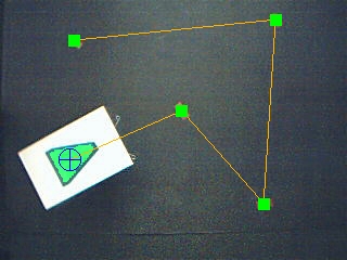
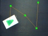
In this tutorial we are introducting the possibility of controlling a Parallax Boe-Bot robot using an overhead camera (possibly one mounted on the ceiling) to control the robot to move around an arena. It is assumed that the camera is stable , looking down onto the robot arena and does not move during the robot execution.The following is what such a potential arena looks like from an overhead camera.
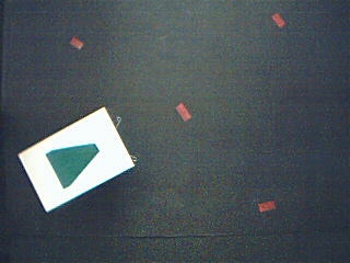
The small red marks are electrical tape stuck to a black metallic surface. The green arrow is a small piece of cardboard with green electrical tape attached in the form of an arrow. This cardboard is placed above a Parallax Boe-Bot in order to easily identify the robot from overhead.
The first step is to identify all the parts in the arena. This includes the waypoints and the robot plus its orientation. First we will start with detecting the Boe-Bot.
Detecting the Robot
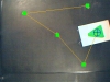
The above image shows the robot under the green triangle. To detect the triangle we use the RGBFilter module set to filter on green.

We can see that the triangle is there but it has some small holes in it. The Fill module with a parameter of zero will fill in any remaining holes.
To smooth out the triangle border and remove some of the additional noise we add the Erode module to produce a cleaner image. We also add in the Blob Filter and set it to eliminate all but the largest blob just in case some other green artifact remains after the erosion. This also provides us with a COG_X and COG_Y array with a single entry that contains the X, Y center of the triangle and is used to determine where the robot's position is.
That completes the green triangle (robot) extraction. Now we need to find out which direction the triangle is pointing so that we know which direction to turn the robot.
Geometric Analysis
Once the green triangle has been segmented from the background we add the Geometric module to run an analysis against the triangle. The value in particular that we are looking for is the ANGLE parameter which gives an indication of orientation of the blob.
When viewing this parameter you will notice that it flickers +=10 degrees or more. This can be reduced by adding in other blob smoothing modules such as Smooth_Hull but this additional precision is not needed for our purposes. Note that the angle is sensitive to the outline or border pixels of the blob. If you make the green triangle ends sharper the stability will also increase.
Once this number has been calculated we save the generated numbers (ANGLE, COG_X, COG_Y) to other variables so they don't get overwritten. This is accomplished using the Statements->Set Variable module. Once this module executes the variables are now called robot_orientation, robot_x and robot_y.
Using the Other->Marker module we revert the image back to the source in preparation for extracting the waypoints.
Waypoint Extraction
Using the Marker module the current image has now reverted back to the original source. We can once again apply the RGBFilter but this time for red.
To again remove the noise we add in an Erode and Blob Filter to reduce the number of blobs to the 4 largest.
The Blob filter module again leaves us with an array of BLOBS with 4 sets of x, y coordinates. To keep these points from getting overwritten by other modules we use the Set Variable module to make a copy of them as "waypoints".
Now it is time to put all the parts together.
Path Planning
The Path Planning module will use the waypoints and the current robot position to plan a path through all the waypoints.
Note that the configuration for the Robot location uses the variables we saved back when detecting the robot position. Also note the use of the variable "waypoints" to automatically provide the waypoints based on a variable as apposed to the manual interface seen directly above.
The graphics created by the path planning module is then overlaid on the current image to view the final planned path.
There remains one problem surrounding the waypoint generation. If we generate the waypoints on each new image frame the robot will obscure the waypoints as it nears them. This will cause a chaotic condition as the system will suddenly lose the waypoint and direct the robot to another. Once the robot moves to uncover the last waypoint it will again be directed to that waypoint causing an oscillation.
To remove this issue we only generate the waypoints once and use the reset waypoints trigger in the Path Planning module to regenerate the waypoint list. This resolution can be seen by the usage of the IF statement in the middle of the pipeline.
Now that we have the planned route we need to determine how and when to move the robot.
Robot Control
The Path Planning module generated a PLAN_ORIENTATION variable which tells us what direction the next waypoint is from the current robot position. We need to approximately orient the robot to match that direction.
Since we know the current robot orientation from the ANGLE variable which was renamed to robot_orientation we can compare that variable with the PLAN_ORIENTATION variable to determine how to turn the robot. Once the robot is in that general direction we can just move the robot forward and repeat the checking process. This control logic is performed using a script entered in the VBScript module.
' moves forward with left and right being opposite numbers (due
' to the flipping of the servos as part of the robot
' construction)
left_speed = 115
right_speed = 105
rev_left_speed = 105
rev_right_speed = 115
stopped = 110
' this is the orientation produced by the path_planning and the
' orientation we want the robot to be at
desiredOrientation = GetVariable("plan_orientation")
' but first check to see if we are running or have completed
' all waypoints.
' When all waypoints have been visited the plan_orientation
' becomes -1.
if GetVariable("interface_run") <> "1" or _
desiredOrientation = "-1" then
SetVariable "left_motor", stopped
SetVariable "right_motor", stopped
else
' get the current robot orientation
robotOrientation = GetVariable("robot_orientation")
' reduce the precision of each of the orientations to
' 20 degree increments otherwise the robot (not being
' perfect in its movements) will spend all its time aligning
' to a degree that it cannot achieve.
robotOrientation = CInt((robotOrientation / 20) ) * 20
desiredOrientation = CInt((desiredOrientation / 20) ) * 20
' calculate the different between the two angles
diff = abs(desiredOrientation - robotOrientation )
' if they are the same (within 20 degrees) just
' move forward
if desiredOrientation = robotOrientation then
SetVariable "left_motor", left_speed
SetVariable "right_motor", right_speed
' otherwise turn in the appropriate direction. Note the use of
' 180 testing to determine which turn direction would
'be fastest.
' This allows the robot to turn in the most efficient direction
elseif desiredOrientation > robotOrientation and diff < 180 or _
desiredOrientation < robotOrientation and diff >= 180 then
SetVariable "left_motor", rev_left_speed
SetVariable "right_motor", right_speed
else
' if we don't turn one way then default to the other
SetVariable "left_motor", left_speed
SetVariable "right_motor", rev_right_speed
end if
end if ' interface_pause
At the end of this script the variables left_motor and right_motor contain the appropriate values to send to the Parallax Boe-Bot.
Parallax Boe-Bot
To send the left and right motor values to the Boe-Bot we use the Parallax_BoeBot module. Be sure to have downloaded the BS2 code into the Boe-Bot that supports the communication protocol used by this module (note that it is the same protocol as the MSRS interface). See the Parallax Boe-Bot module for more information.By specifying the Left and Right motor variables we can now send the motor values to the Boe-Bot.
Now let's review the processing pipeline.
Processing Pipeline
Notes:
1. The first module "Button_Interface" provides a simple Start and Stop button interface to easily control the robot
and reset waypoints. This interface will popup immediately once this robofile is loaded.
2. The "Set robot_orientation = ..." is used to rename generated variables to other names so that they will not be
overwritten by utilizing the same module again.
3. The IF statement controls when the waypoints are regenerated. This is linked to the 2nd Reset button in the Button_Interface module.
4. The Math module is used to merge back the green triangle over the original image. We noticed the triangle would
sometimes disappear based on the lighting of the arena. This helped us keep an eye on how that segmentation was
working as the robot moves.
Video
 (2.3 MB) Video of the BoeBot moving through each of the waypoints as seen from the overhead camera.
 (2.1 MB) Different starting location and 3 point light source.
Your turn ...
![]() Download the Path Planning robofile. Note that the
Parallax module (last module) is disabled as you will need to configure that
module for your COM port before enabling (to enable simply unpress the Disable button
when that module is selected in the pipeline list). Also note that the
red markers are only processed once when the reset button is pressed as it is assumed that the
markers remain stationary during the robot operation.
Download the Path Planning robofile. Note that the
Parallax module (last module) is disabled as you will need to configure that
module for your COM port before enabling (to enable simply unpress the Disable button
when that module is selected in the pipeline list). Also note that the
red markers are only processed once when the reset button is pressed as it is assumed that the
markers remain stationary during the robot operation.
The End
That's all folks. We hope you've enjoyed this little adventure into an application of machine vision processing. If you have any questions or comments about this tutorial please feel free to contact us.
Have a nice day!
| New Post |
| Path Planning Related Forum Posts | Last post | Posts | Views |
| None |