
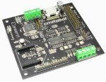
cmRobot Element
The cmRobot_Element module provides an interface from RoboRealm to the cmRobot Element robot controller. The module provides an interface to configure the appropriate communication port and speed to the controller and allows you to view and modify settings by using the GUI based sliders and text editing areas. To automatically specify the values you should select variables from the dropdown menus that will contain the values that will be sent to the robot. Note that once variables have been selected manual controls are disabled.
Interface
Instructions
1. COM Port - Select the appropriate COM Port that the Element is connected to. You will only see COM ports that are recognized by your computer. Note that direct serial connections normally use com ports lower than 4 whilst virtual COM ports created by bluetooth connections are much higher. Check your bluetooth configuration manager to see which port your robot communications is installed on. Note that this will be an Outgoing port.
2. Baud Rate - Select the appropriate baud rate. 19200 is the default speed used. Select a higher baud rate if you want to and can increase the communications speed. Be aware that wireless devices may not support the full baud range of the Element board. If you accidentally set the baud speed to something faster than your wireless device supports you will have to connect the Element directly to your PC in order to change the baud rate to a lower setting.
3. Battery - once the Element is communicating with RoboRealm you can turn on the battery monitor in the Other tab to test the connection. Do this by simply selecting the Battery area checkbox in the interface. The power level will be shown in blue bars with the number of volts in the "Current Value" textbox. If you want to use the volts within other areas of RoboRealm select a variable that the module will write the number of volts to. This variable will then be updated each time the Element module is run with the current voltage of the robot.
4. Motors - After specifying the COM Port you should be able to move your motors by dragging the sliders to the right or left or by specifying a number within the "Current Value" text box in the Motors area. If the motors do not move (or whine) check your COM Port setting and/or board connections.
5. Variables - Select the appropriate variables that contain or will contain the position value that will be sent to the robot. This is used to automatically change the motor values based on your VBScript (using the SetVariable function) or Extension based program. See Variable Control for more information on how to programatically move the robot.
6. Current Value - To manually set the motor position type in the appropriate number (-100 to 100, 0 is the default neutral/stop) into the text area or use the slider to adjust the value. The servo position will be updated as appropriate.
7. Min/Max Limits - You can also use the min/max limits to ensure that even if the variables specify large or low values (due to programming errors) that the robot does not actually attempt to move the motors above or below the specified limits. This can be used as an additional precaution in case you are testing your robot in a precarious position.
8. Servos - Using a similar interface as the motors you can specify the position for up to 6 servos. Once you do so you will notice one of the Digital IO pins become disabled. This is due to the servo pin and IO pin being the same pin. While there are 10 IO pins only 6 can be used to control servos. Note that additional power supply may be needed if you are using 6 servos.
You can use the slider bar to move the servo or type in a number directly in the "Current Value" textbox to move the servo to that position. To move the servo automatically select a variable that contains or will contain the value to move the servo to.
9. Analog Pins - The Element provides for 5 user analog inputs. (There is actually one more but that is tied to the battery). If you enable the Analog pin you will notice the values in the corresponding read only text boxes change based on the voltage across those pins. If you have a distance sensor connected to an analog pin move your hand in front of the sensor to see these values change. By specifying a variable in the corresponding dropdown you can access that value elsewhere in RoboRealm in order to make decisions about the sensors value.
10. Encoders - To enable the encoder area click on the group checkbox. This will enable the encoder readings and display the number of encoder ticks that the robot has traveled. If you enable this area and then move the robot using the Motor sliders you will see the encoder values change depending on how fast the robot is moving. Specifying variables in the dropdown will cause those variables to be set to the current values read from the robot. Also note the "Reset" button that can be used to reset the encoder values on the robot to zero.
11. Digital IO - In addition to the 4 analog inputs the Element provides 10 digital input/output pins. Note that if you are using servos some of those pins will already be used. The remaining pins can be used to drive outputs or receive inputs.
Each pin can either be set as an input or output. Do this by selecting the "in" or "out" radio button next to each pin. If you are specifying a pin as an output you can manually control the output by selecting the checkbox which will then turn that pin high or low.
For input pins the checkbox (in a disabled state) will reflect the high or low states of the pin.
To automatically send or receive a bit select or type in a variable that will be set if the pin is configured as an input or read if the pin is configured as an input. Note that you can tell RoboRealm which bit of the variable you want to set/get by using the provided bit dropdown. If no bit is specified the entire value is considered during a set/output.
As an experiment, you can connect an LED to pin 0 in the Element. Then select the pin as an "out" and by checking and un-checking the checkbox you can make the LED blink under manual control. If you then select the IMAGE_COUNT variable (which holds the current image counter) as the variable and select Bit 0 the LED will blink for every two frames captured. Selecting successively higher bits will slow the blinking by a factor of 2 for every bit.
12. Direct Serial Command Variable - As the Element has many additional capabilities not reflected in the GUI the direct serial command variable will send the text contained in the specified variable to the Element and place the returned results back into that same variable. Thus you can specify a variable (or type a new one) into the provided textbox and set the value to any of the serial commands that the Element understands. For example, you can use
SetVariable "my_command", "i2c r 4 1"in a VBScript module to query the line following sensor.
13. Stop - press the stop button to quickly stop the motors. The motors controls will then be disabled (in case variables are selected) and will only restart when you click the same button again (now renamed to "Start").
For more information
cmRobot Element Controller
| New Post |
| cmRobot_Element Related Forum Posts | Last post | Posts | Views |
| None |