
RoboteQ Motor Controller
The RoboteQ Motor Controller module provides an interface from RoboRealm to the RoboteQ Motor Controllers. The RoboteQ line of Motor Controllers feature a high-performance microcomputer and quadrature encoder inputs to perform advanced motion control algorithms. Additionally, digital out, digital in and analog in are provided on most boards.This module provides an interface to configure the appropriate communication port and speed to the controller and allows you to view and modify settings by using the GUI based sliders and text editing areas. To automatically specify the values you should select variables from the dropdown menus that will contain the values that will be sent to the controller. Note that once variables have been selected manual controls are disabled.
The module is not meant to provide as comprehensive configuration that the Roborun+ application distributed with the RoboteQ controllers does, but, instead, provides an interface to those parameters that change within normal execution. To change a controller's default configuration, exit RoboRealm, use Roborun+ to make the needed changes, exit Roborun and then start RoboRealm.
Please note that depending on the type of controller you are using you may have more or less functionality that is represented in this module. Pins are often shared amongst different capabilities so take care not to overlap pins. For example, Analog 1 is the same pin as Pulse 5 and Digital Input 5. Thus if you use Analog 1 you will not be able to use Pulse 5 or Digital Input 5.
Also note that prior to using this module your pin needs to be configured correctly in RoboRun. For example, as Pin 5 can be used as an a digital input and analog input, you need to use RoboRun to configure the pin to the appropriate mode. If you configure the Pin as a digital input and attempt to use it as an analog input, the value will always be zero.
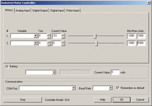
Interface
Instructions
1. COM Port - Select the appropriate COM Port that the Controller is connected to. You will only see COM ports that are recognized by your computer.
2. Baud Rate - Select the appropriate baud rate. 115200 is the default speed used.
3. Battery - once the Controller is communicating with RoboRealm you can turn on the battery monitor to test the connection. Do this by simply selecting the Battery area checkbox in the interface. The power level will be shown in blue bars with the number of volts in the "Current Value" textbox. If you want to use the volts within other areas of RoboRealm select a variable that the module will write the number of volts to. This variable will then be updated each time the Controller module is run with the current voltage of the robot.
4. Motors - After specifying the COM Port you should be able to move your motors by dragging the sliders to the right or left or by specifying a number within the "Current Value" text box in the Motors area. If the motors do not move (or whine) check your COM Port setting and/or board connections. See Variable Control for more information on how to programatically move the robot.
5. Variables - Select the appropriate variables that contain or will contain the position value that will be sent to the motors. This is used to automatically change the motor values based on your VBScript (using the SetVariable function) or Extension based program.
6. Current Value - To manually set the motor position type in the appropriate number (-1000 to 1000, 0 is the default neutral/stop) into the text area or use the slider to adjust the value. The servo position will be updated as appropriate.
7. Min/Max Limits - You can also use the min/max limits to ensure that even if the variables specify large or low values (due to programming errors) that the controller does not actually attempt to move the motors above or below the specified limits. This can be used as an additional precaution in case you are testing your robot in a precarious position.
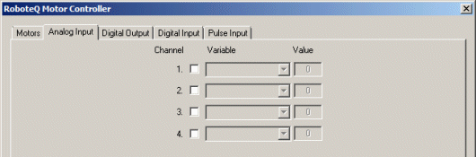
8. Analog Input - The module provides for 4 user analog inputs. If you enable the Analog pin you will notice the values in the corresponding read only text boxes change based on the voltage across those pins. If you have a distance sensor connected to an analog pin move your hand in front of the sensor to see these values change. By specifying a variable in the corresponding dropdown you can access that value elsewhere in RoboRealm in order to make decisions about the sensors value.
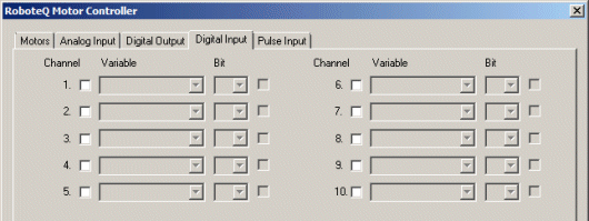
9. Digital Input - In addition to the 4 analog inputs the module provides 10 digital input pins.
The checkbox (in a disabled state) will reflect the high or low states of the pin.
To automatically send or receive a bit, select or type in a variable that will be set based on the pins value. Note that you can tell RoboRealm which bit of the variable you want to set/get by using the provided bit dropdown. If no bit is specified the entire value is considered during a set/output.
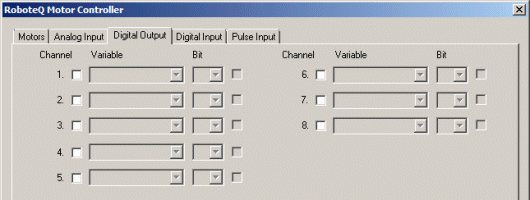
10. Digital Output - The module provides 8 digital output pins.
As an experiment, you can connect an LED to pin 1 in the Controller. Then by checking and un-checking the checkbox you can make the LED blink under manual control. If you then select the IMAGE_COUNT variable (which holds the current image counter) as the variable and select Bit 0 the LED will blink for every two frames captured. Selecting successively a higher bit will slow the blinking by a factor of 2 for every bit.
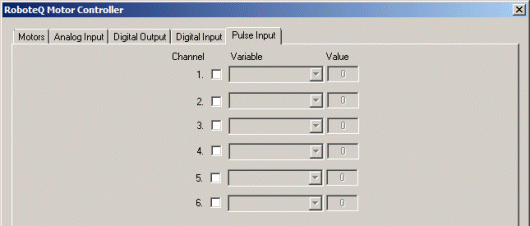
11. Pulse Input - Similar to the Analog Pins you have access to up to 6 pulse pins that are typically driven from an RC type controller.
12. Stop - press the stop button to quickly stop the motors. The motors controls will then be disabled (in case variables are selected) and will only restart when you click the same button again (now renamed to "Start").
For more information
NxtGen Brushed DC Motor Controllers
| New Post |
| RoboteQ_Motor_Control Related Forum Posts | Last post | Posts | Views |
| None |