Hi dear Steven, good morning.
How are you ?
I hope everything is going well with you.
My name is Romulo and I speak from São Paulo (Brazil). I am professor at Federal University of ABC and I am currently developing a project in partnership with a corporation, whose the goal is to measure machining (in this case drills) tool wear of tools in process.
Summarizing briefly, I have experience with Matlab for Image Processing, however I've decided for the use of your software (Roborealm) for this project. At the moment, I already developed some algorithms and now I have some troubles with the image processing algorithm for measuring the tool wear. I will describe my problem in details and if you could help me with this task I will be everlasting grateful.
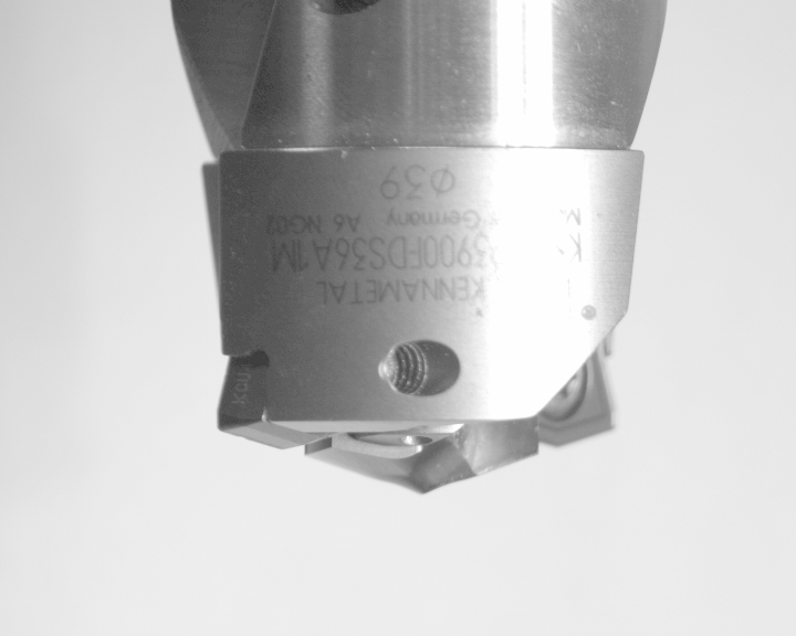
For the current project, I have to main goals to be developed. The first one is to measure the area of wear in the face of a tool insert. I've tried to apply threshould techniques, but unfortunately I was no able to measure it properly as normally I do using matlab, for instance. Below I am attaching the image to be processed.
As shown in Figure 1 above, the circled area is my target and it shows the tool wear during the machining process at a real shop floor. As mentioned before, the issue here is How to detect and measure the wear area using commands of your software ?
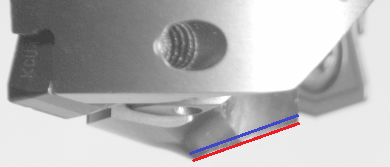
Furthermore, from the measurement of the wear area I would like to create to lines, as shown in the figure 2 below.
The first line in red is should highlight the theorical tool edge without any wear and the second line should be constructed parallel to the highest wear point of the tool. I tried to use Hough filter to created them, however I was not able to used the command properly yet. Finally, my goal is to measure the distance between these two lines.
I am also attaching the original image for processing
  
|
|
Romulo,
The solution would depend on how the drill bit can be imaged. For example, is it always assumed the bit is in the same orientation against a while background? If so, one can use probes to determine the line ... see attached.
If not, additional features will need to be determined in order to determine the position of the bit ... this will be needed if the bit rotates, translates, etc. from the view that you have attached.
To determine the second line will require more knowledge of what a non-worn bit looks like. How do you know when the wear is getting complete? This can also be determine relative to some other feature of the drill bit (perhaps the screws) but more about how the images will look needs to be determined.
Normally, one captures at least 20 images to test for a technique and then another 100 to test that the solution actually works. This is needed in order to determine if the assumptions made about how the image looks hold across normal operation.
You can also explain more about how you did the solution in Matlab since that helps us understand what assumptions made will keep across many images.
STeven.

 program.robo program.robo
|
|