So I think this is probably possible with this software (just started playing with the demo of it, so far it's impressive!).
I'm looking to measure a distance between two lines to set a reference dimension (basically # of pixels = known value (1.5 in this case), and then measure 2 other dimensions and compare to a minimum allowed value. I can do the calibration dimension/comparison externally if needed, I'm trying to figure out the operations/order of operations that might work best for this problem.
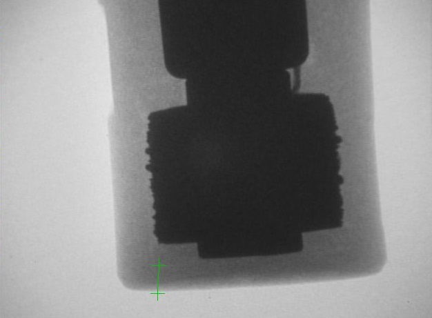
Attached is an image file from an X-Ray camera that I'm using to inspect a magnetic probe.
First, I'm looking to get an aligned dimension from the lowest, darkest part (which will be the calibration value for pixels to mm, it's an exact 2.0mm), short edge to short edge. I'm thinking the image needs to be aligned first, it can reference any part of the image.
Second I want to measure the aligned distance from each edge of the above reference dimension to the nearest outer edge (the lighter gray area), and ideally compare it to a minimum allowed value (can do that part externally).
The goal is really to determine how centered the dark area is within the lighter gray area, but also to determine if the centering is significantly off (hence min value).
The image shown always appears similarly in camera, but the vertical angle may change by up to maybe ±20 degrees from vertical.
Also, ignore the green line on the image, this was a screen grab from the camera, that would normally not be there.
Thanks!

|
|
Alan,
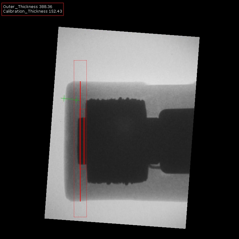
Yes, this is a common use of the application. In your case, the first module will align the image in a known orientation such that when presented with a similar (but not exact) image it will place the main part in the same orientation and location. The Orient_Image does this quite easily by taking into account the image content and edges of the part.
Once this is done, we can use the Thickness_Probe to measure the distance between edges. The probes assume a small location window so its important the part appears more or less in the same location/orientation ... which it should if the Orient_Image module is doing its job.
I've attached a sample robofile which measures the inner and outer part and displays them as two variables in terms of pixels based on the image resolution. Note the use of the adaptive threshold module to better isolate the outer more faint area. Its a first attempt that will need to be reviewed when more images are tested but should serve as a starting point.
As always, this is a simple 1 image solution that needs more testing based on other images before putting something like this in production.
Cheers,
STeven.

 program.robo program.robo
|
|