|
Barcode decode anomaly
Pete from United States [56 posts] |
12 year
|
Hi STeven,
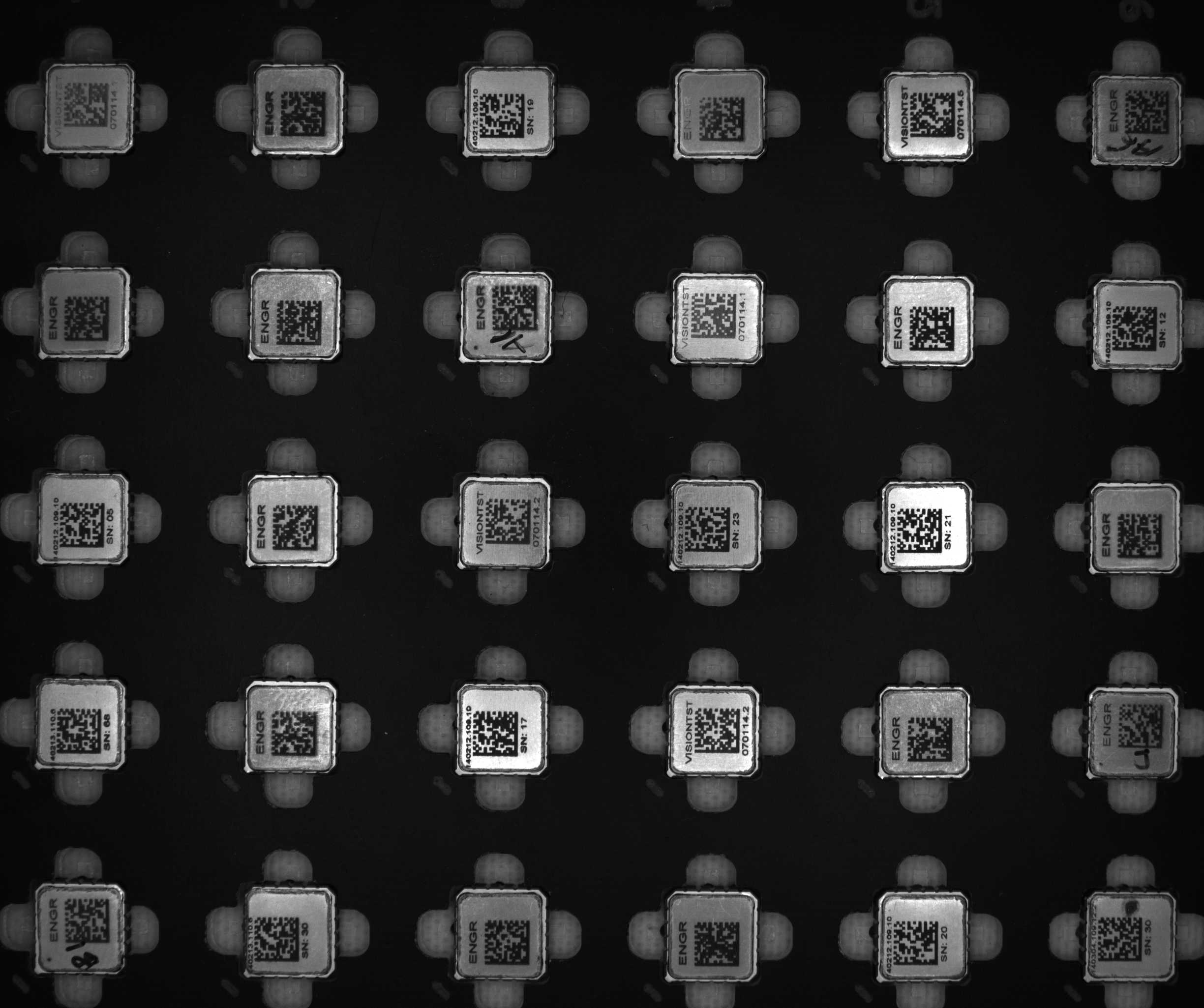
I'm seeing something when using the barcode decode module. What I have is an image with 30 2d matrix barcodes. I do little processing on the image so that the barcodes came be decoded. After the image processing the image is copied to the clipboard and then the following routine is performed. For each of the 30 positions a variable is set and the following is performed
if A1 is null OR A1 = "0" then
Set A1 = 0
Crop
Barcode Reader
if DATAMATRIX_MESSAGE is not null then
Set A1 = DATAMATRIX_MESSAGE
Set DATAMATRIX_MESSAGE =
end if
end if
This sequence is repeated for the 30 positions selecting a new crop area. This is issue that all barcode may not be decoded and the plan is to tweak with the adaptive threshold parameters or change some other setting if the barcode module is having difficulty with decoding some positions.
What happens is position A2 can detect a 2d matrix code (purple box displayed) but is unable to decode. Ok, so no issue on to the next position. Most decode properly, but I get to another position where it can't decode, what is happening is the purple box from the position A2 is showing in the image. Also it seems like the variable DATAMARIX_MESSAGE is not getting properly cleared with the Set command as on positions not decoding I'm getting the same decode value appearing in those variables as was in A2 after tweaking my light source or changing some Adaptive threshold values.
Why is the purple detection box showing processing further down in the pipeline?
I have attached the script I am using, line 21 is where the detect occurs but no decode. Then in lines 206, 246 & 256 where it is trying to decode a new crop position the purple box from line 21 appears. Also any read from the clipboard will also show the box in the lower left corner area.
Also attached is an image file.
Thanks for any help,
-pete

 program.robo program.robo
|
|
|
|
Pete from United States [56 posts] |
12 year
|
Hi STeven,
Here is some additional clarification. In the attached script it uses the attached image file. I have the settings so that barcode module recognizes but can't decode. In line 8 why is the purple box from the 1st barcode still being displayed?
From the original script you will note that once the barcode has been decoded the script will skip analysis of that crop area. This I would assume then require less time through the loop next time. I read back the 30 variables to determine if all have been decoded, if not I plan to tweak some parameters to improve the ability to decode, as there may be slight variations in the marking process.
I also mentioned that datamatrix_message was being seen in other parts that had not be decoded thus the command to set variable to clear the datamatrix_message variable after the variable was set. When the purple box appears I assume the variable datamtrix_message should still be null is that correct?
Thanks,
-pete

program.robo
|
|
|
|
Carl from Your Country [1447 posts] |
12 year
|
Pete,
thanks for the images and the robofiles. That will give us something to work with.
The purple box is more of a debugging tool. It shows that the module recognized that there is something in that spot that looks like a barcode but it CANNOT decode the information correctly in order to provide a result.
We'll check on the variable settings and ensure that they are null when purple box is indicated and removed when nothing is detected.
We've also fixed a problem that was preventing one of the codes from being detected and will be taking some time over the weekened to look into why more of the codes are not being detected. It seems that the purple box is a little skewed which might be an indication of why the decoding process is failing.
We will also look into why the codes are not detected unless a different threshold parameter is used. In theory, it should detect the code regardless of the threshold settings (within reason) so we might be able to make your entire process a lot simpler by correcting that detection in the module itself.
There will continue to be a bit of a problem in terms of aligning what gets decode with what part of the image. I understand why you are cropping and testing which solves that problem ... we may introduce an easier way to accomplish this since it is a technique we've seen repeated a couple times.
I was also going to mention the use of the Marker module instead of write/read to clipboard but it looks like you found that!
Give us a chance to see what we can do and I'll update you on this post.
STeven.
|
|
|
|
Pete from United States [56 posts] |
12 year
|
Hi STeven,
As far as decoding I have good success, in the last example the lighting was adjusted to give a poor image, and I did not have any adaptive threshold processing trying tp replicate if I have some parts that may not have good contast to show the duplicate detection box appearing mulitiple times.
Over all the majority of parts are being decoded on the first pass through the loop. We have been working on a light box to evenly light all the parts.
As mentioned it is when parts whith marginal marking that are not decoded on the first pass where I see issue with same number being updated for the wrong location.
On a side note is it possible to single step through the pipline?
-pete
|
|
|
|
Carl from Your Country [1447 posts] |
12 year
|
Pete,
We've completed our tweaking of the Barcode module specific to the DataMatrix code. Currently with a couple additional modules, we are able to decode 100% of the datamatrix codes included in your image. Naturally, this is just one image and the resulting robofile should be tested on many more to increase your confidence that the solution works.
A couple changes were made that are new:
1. The barcode detection uses adaptive threshold (for DataMatrix and Maxicode) within the module to extract out potential codes. We've exposed the WindowSize and Offset into the Barcode interface. Should you need to tweak the adaptive thresholding you can change those numbers directly. To see what you are doing, you can now select the "Show" button in the Segmentation area to see what the result of the adaptive threshold is to allow for correct tweaking of those values.
2. We've also added a min and max size filter to remove those objects that are too small or big to be barcodes. While not really needed, these help to remove unwanted blobs from being tested and increases the speed of the module. Since you have quite a large image we wanted to add this filter to help improve processing speed ... which it does quite nicely.
3. There was a problem in the actual decoding logic that would cause some instability in the decoding. Thus if you noticed codes that would flicker between green (correctly decoded) and purple (bad decoding) that has now been fixed.
4. In addition to the error fix, we changed the way the datamatrix codes are being extracted to be a lot more adaptive which really helped to extract out the correct information without needing any changes to the adaptive threshold.
5. Finally, we added in a couple modules before the barcode module to surround each potential code with a border that avoid the datamatrix code from being connected to the written slashes/lines/etc. Because of the way the code is extracted, if the code is touching another dark area the module doesn't know how to extract out the code correctly. Because your application appears to present the barcodes in a good top down perspective, we used a trick (maximal edge within 45 radius) to identify potential codes and surround it with an average of the area. This then allows the adaptive threshold to isolate the code as needed allowing for correct detection.
To answer one of your previous questions, the purple (and green) lines will be drawn in the second iteration of the pipeline to avoid those lines from becoming part of the image and affect successive processing. Because of that, you'd see the squares appear in what appeared to be wrong places. To avoid this, unselect the "Display As Annotation" which will draw the line in the current graphic and avoid that confusion. Or just select the "Test Box Color" to nothing.
Note that the variable names have also been corrected to increment from DATAMATRIX_MESSAGE, DATAMATRIX_MESSAGE_2, DATAMATRIX_MESSAGE_3, etc. So if you test DATAMATRIX_MESSAGE_30 and get a blank result, you know that one of the codes
didn't get decoded correctly. Alternatively, you can check DATAMATRIX_COUNT (new variable) that will indicate the
number of detected codes.
If you need to know WHICH barcode didn't decode correctly we can also add the X,Y coordinate of the data matrix centroid that will help in this determination. Let me know if you need that.
See the attached robofile for these improvements and please download the latest RR version for these updates.
For stepping through the pipeline, just click on each module in the pipeline which will show the pipeline up until that point.
STeven.
program.robo
|
|
|
|
Pete from United States [56 posts] |
12 year
|
Hi STeven,
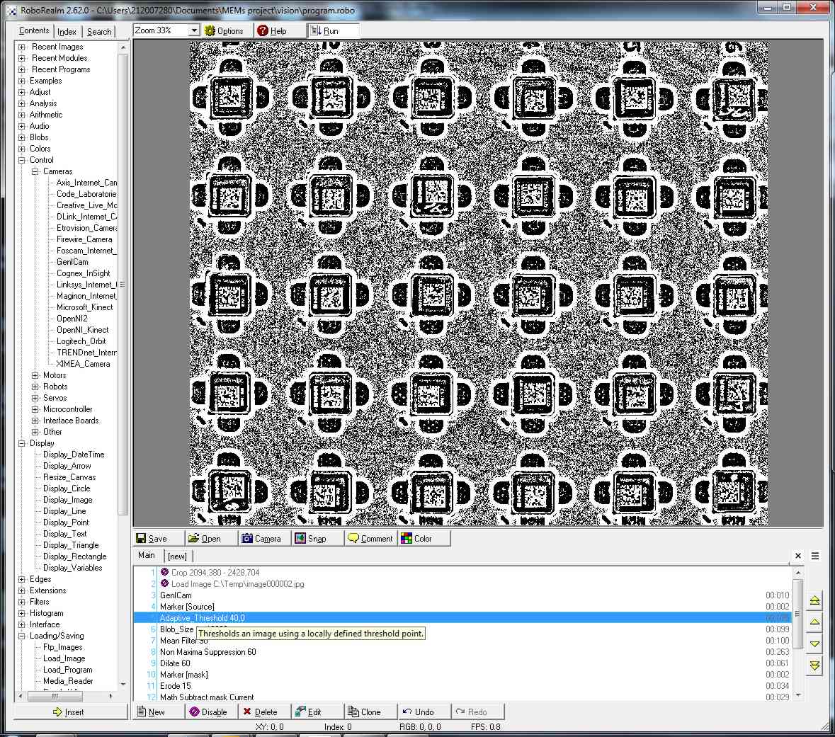
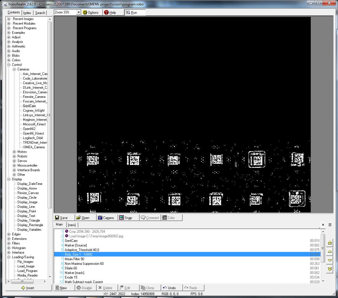
Thanks for update on the decoding issues. Having an issue with the new update. Using the script you provided is doing the following. When selecting the Blob size module I only see the bottom 2 rows, the top 2/3 of the image is black, see attached images.
Img1A show the display for the Adaptive threshold, then for the blob size it shows Img2. I have tried changing parameters in the blob setting but can never get any thing to show in the top 2/3 of the image. The only change was to disable the image load and add the GenICam module at the top. If I go back to the static image all the locations show up.
As for determining if a location does not decode yes it would be helpful to to know which position. I assume I could determine the 30 locations from one of the prior modules, then compare the barcode for that general location decoded. What do you think of the approach I took which defined 30 crop areas and once decoded skipped the next pass through.
Still working with the program you sent and it is decoding 27-29 of the 30 parts each time through the loop. It is interesting that you where all to decode all locations, I'm using the same parts and just changing the lighting.
Looks like tweaking with a few camera parameters (gain and exposure) can help with the image dynamics, thus the question about being able to set these parameter with the GenICam module, is this possible?
Thanks for all the support,
-pete
 
|
|
|
|
Pete from United States [56 posts] |
12 year
|
Hi STeven,
Am I correct in assuming that when the barcode module decodes the barcodes it is somehwat in a ramdom order? If so then the barcode position would be required to assign the barcode to a known position. Also each time through the loop it seems that data for some message #'s change, this happens when the datamatrix count also changes when not all 30 positions are decoded.
Thanks,
-pete
|
|
|
|
Carl from Your Country [1447 posts] |
12 year
|
Pete,
As mentioned, one image is never enough to determine a correct solution. As you have found out, even if you breath on the camera, things can change. Unless a solution is tested on many images you can never guarantee that it works as expected.
What has happened is that you changed the lighting. That always causes things to change by quite a bit. Based on the screen captures, what has happened is that the adaptive threshold is creating too many objects (+30,000) for the blob size module to handle. You should be able to solve this by typing in something like 100 for the Min threshold in the Adaptive Threshold module. This will cause all the darker areas to automatically be made a single solid white object which will greatly reduce the number of separate blobs. This should fix the blob size module. If not, can you post that image here? Its always helpful to have an image to test rather that guess at what might help.
The 'random' order is in fact not random but to you it appears so. What is happening is that the barcode module will scan the image from top to bottom, left to right order. When it encounters a single pixel of a barcode, that's the first barcode. Now, because the image is again flickering (i.e. pixels around the barcode are changing intensity ever so slightly) a barcode may suddenly move up or down a single line which is sufficient to change the ordering. That's the issue that I was referring to earlier in terms of needing the X,Y location of the barcode (I was anticipating this issue). This change of detection is what is causing the array to also change ... as soon as a barcode is not detected or detected in a different order it will change that array drastically.
Your idea on cropping the image to isolate certain areas is right on. In fact, we just released a beta version of a "split image" module which should really help with this. What this module does is to split an image in equal portions and then present that image to the pipeline as if it were an individual image. Thus, by monitoring the SPLIT_IMAGE_ID you can tell what part of the original image is being processed and instead of looking amongst 30 barcodes, you are instead dealing with the absence or presence of just one. Hopefully this module will shorten the pipeline from needing 30 crop modules to do the same.
I've attached an updated robofile with that module included to show how it can work.
As for the changing of exposure and/or shutter speed, that should be possible by changing the setting in the Advanced tab. As each camera uses a slightly different way of doing this exposing that in a reliable control has proven complicated. We do have the exposure control in the second tab but that's not guaranteed to work since it makes some assumptions about the control name that may not be true in all cameras.
We'll look into adding in [expressions] into those settings to allow for settings to change based on RR variables.
If you continue to have issues in barcode recognition, let us know and we can probably help further.
STeven.
program.robo
|
|
|
|
Pete from United States [56 posts] |
12 year
|
Hi STeven,
I tried your new code, pretty neat the split mode. This mode seems to very fast. There is an issue. How do I get the decoded values, each of the 30 processed images updates the same DATAMATRIX_MESSAGE variable. I would assume that each processed cell would update its own variable. I see each of the cells being displayed very quickly when the barcode mode is selected. Am I missing something on how to get the values?
A note on the lighting, I set it to a very poor low level on the test image I sent you to try and get the 2 purple squares to show up. I have been finding out that the lighting is not as important and not as sensitive as I first thought. I have a rectangular ring with 20 LED's and I can very the supply voltage by several volts with not much impact to the parts being decoded.
Prior to running this latest RR program I was using the 30 location crop method with very good success with the FPS showing ~3. With you new split method it is running at 15+.
Also your explanation of the the blob processing explained why I was not seeing all 30 locations, after adjusting the min value as you mentioned now I can get all location to show up.
Really impressed with the latest split mode, just need to be able to get the individual codes. A question on the display when the barcode module is selected. I see the 30 images being displayed very quickly on the screen, once in a while I will see a purple square for an image but it is running so fast I can't determine which cell is having the issue. Is there a way to have it selectively display the results of a specified cell?
As for changing the gain and exposure on the a GenICam camera, yes I can manually change it in the module, but was looking for was way to change via the API interface.
Thanks, things are looking real good,
-pete
|
|
|
|
Pete from United States [56 posts] |
12 year
|
Hi STEven,
Another possible issue, with the latest program I am unable get the 30 scrolling images to stop. When selecting any module I will very briefly see it flash before the 30 very quickly.
You may ignore this as I see that when the Block Id is non-zero the image cycling stops. Still need to get the individual codes.
Thanks,
-pete
|
|
|
|
Pete from United States [56 posts] |
12 year
|
Hi STeven,
Other issues when using the split image module. When a value is set for the block id parameter the image in the split module or any module after will not update, no live image update.
Also need to coorect previous comment. When the block id parameter is 0, image cycling mode the FPS reads high >15, I might assume that each split cell is being treated as an image and then messing with the FPS calculation. If the block if parameter has a value then the FPS drops to 1.4. Here I thought I was actualy getting that from my camera, but I don't believe that was the case.
Thanks,
-pete
P.S. I guess by now your getting tired if seeing posts from me :)
|
|
|
|
Carl from Your Country [1447 posts] |
12 year
|
Pete,
On the exposure, what you can do is enter [my_variable] with brackets into the exposure text field (assuming Image tab here) which tells the module to grab the value from a RoboRealm variable instead of taking the value literally. You can then set this variable via the API or from many other modules. We are working to add this to the Advanced tab too in order to set any parameter in this same way.
Your assumption on the FPS is correct. The FPS indicates how many frames get to the end of the processing loop. Because the split image creates many more images in the pipeline the FPS will be much higher and not correctly indicate the actual number of camera frames captured. Unfortunately, this is one of the side effects of the split module. Since this is confusing and causes the appearance of a fast pipeline which it isn't we updated the FPS to avoid this issue.
Setting the block id will now also grab live images as apposed to remaining static.
The big change this round is how the Split Image module works. We changed it into a compound module which will repeat those modules contained within the split start and split end position. Beyond the end split the module will reassemble the images into a single large image. We found this to be a MUCH better way to monitor the result rather than looking at the smaller sub images quickly flip by. The block index still does what it did but now zero is meaningless as it is always processing all images but only showing the image specified by the block id.
We also added a variable selection to the module to ensure that variables can be renamed to different names instead of being overwritten. I've attached the new robofile that now will generate the desired variables even if a barcode is not recognized in a particular split sub image.
Actually, no, we're quite happy to read your posts. Its always great to have a real-world use case to improve/test the modules against.
If you find that you still get purple boxes around barcodes and can capture those images (press the snap button and then save ... or press CTRL-C while focused in RR and paste the image somewhere) we'd again be happy to review those in hopes of improving the decoding.
See 26.62.3 for these updates.
Thanks,
STeven.
program.robo
|
|
|
|
Pete from United States [56 posts] |
12 year
|
Hi STeven,
Comments on the latest changes, as always seeing many improvements. This looks like it got broke, in the split module the 'Label Image Number' when checked no longer shows on the image. It shows in the module preview image but I thought I recall it being displayed on the scrolling images. Would assume it show the image cell # on the image being displayed by the block_id selection.
In the program file you set, I see one issue. In the real world it is possible that that all locations do not decode on the first or one pass. As each time a new image is acquired with slightly different dynamics that may or may not help when trying to decode the bar code. In the real world and parts have variation. With the present program I would read the 30 variables and find that only 29 decoded, I can now tell which one did not decode with the present method which is a big plus. Now the next time through it may decode if it were right on the border. But in this process you also re-processed all the other locations and different location also on the border may not decode. Kinda see where I going with this, you have to decode all locations properly to get the 30 code back. This is could be handled in the software reading the codes where it could keep track of locations that ready decoded properly which would work, but you are using processing time to re-process locations that have already been decoded.
The method I have mentioned in the past would skip locations that have been decoded and could then re-process other locations quicker that might be on the border of being decoded, thus my comment about being able to twiddle with the camera gain and exposure values to dynamically change the image dynamics. I am finding that only very slight changes can help decode border line locations.
Overall I would say it is doing a really good job and decoding on the 1st pass. I'm trying to get samples parts and run as many as I can, I would have to say the batch I currently have would has the biggest variation and the program is working quite well.
I still may stick with the crop method as it is working quite well being able to decode all positions within a second. I currently have an adjustable light source that can tweak to help with possible problem locations, again thus the ability to twiddle with the camera settings dynamically.
I'm still trying to the GenICam module to change gain or exposure by replacing the value with variable as you indicated. I can see the variable change but something is going on where the images may stop updating and I seem to have to enter the module and exit to get things going again or wait quite awhile. I need to create a new program with no barcode processing to dig into this.
Thanks,
-pete
|
|
|
|
Pete from United States [56 posts] |
12 year
|
Hi STeven,
Here is an update to changing the camera gain in the GenICam module. I have a simple program
1) GenICam
2) Watch_Variables
From an external program I change a variable CAM_GAIN which I can see change in the watch variables module. In the GenICam module under the Image tab I have the Gain entry set for [CAM_GAIN]. After changing the gain value no change in the image, but if I open the GenICam module and exit the new camera gain will take effect. I have tried disabling and re-enable the module seems to only work when the module is opened and then closed. Also stopping and starting the pipeline does not work.
Thanks,
-pete
|
|
|
|
Carl from Your Country [1447 posts] |
12 year
|
Pete,
Thanks for the test. The Genicam module was not paying attention to variables changing. This has been fixed.
Note, as you find ones that don't work (i.e. the purple square) please post them here as there is always things we can do to make it even more robust. I realize that changing the gain/exposure can help but ideally we'd like to make the extraction as robust as possible so things like that are not needed. No way to know if this is even possible without seeing why those images are causing problems still.
Also, the Split Image module was updated to fix a couple issues ... but I think I agree with you on sticking with the Crop method as that seems to also accomplish what you need.
STeven.
|
|