|
path planning
arindam [8 posts] |
18 year
|
hey, nice work people awesome s/w that to for free,
i was going through your path planning tutorial, i just hooked up my toy car with my PC, and thought it would be cool to put in some image processing. i got the .robo file given as a part of the path planning tutorial.
added a 'crop module' to fit my picture bt i cant seem to work the ' non -zero' pixel .
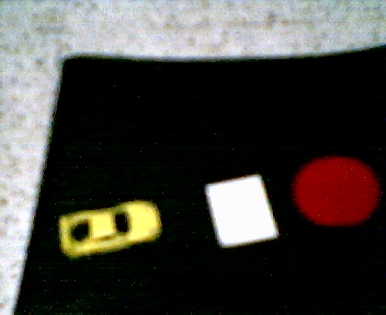
basically i am trying not to hit the white marker.
and reach the red spot.
any help will be great i am sittin at it for quite a while cant seem to figure out any way..
(one more thing.. the frame rate diminshes to almost 1 when i run the program, is it a problem with my system. also for each frame the program performs a new 'path planning step. so it might lead to development of multiple paths???" am i wrong...
here is the pic... the .robo is available with the tutorial.
i am sure all of you are pretty busy.. but any help will be welcome.
thnks...
|
|
|
|
arindam [8 posts] |
18 year
|
here is the pic

|
|
|
|
arindam [8 posts] |
18 year
|
|
hey!! rizo here i have got much of it done.. i will put up the >robo soon!!!!
|
|
|
|
Anonymous |
18 year
|
Rizo,
The frame rate will diminsh if you don't have the correct hardware connected. For example, the tutorial uses the Parallax Boe-Bot ... if you don't have this hardware connected correctly then the system will really slow down as it tries to connect to that absent hardware (it's an OS issue).
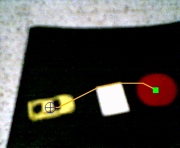
We went ahead and used your provided image and changed the robofile from the tutorial a little. We remove the BoeBot module, changed the first color check from green to yellow, added in a threshold and invert to change the black area to a white area (thus the non-zero path i.e. white is now valid) and added a new overlay feature in the path planning module (you'll have to download 1.8.6.8) so that the source image is overlaid with the graphics to produce the resulting image. Note the included robofile includes your image so you should just be able to load that robofile directly and see what mods we did.
Our result 
STeven.
 program.robo program.robo
|
|
|
|
still problem
arindam [8 posts] |
18 year
|
hey STeven. rizo here, i have been at this problm for quite some time now intially i thought it must have been the hardware but a little tinkering and i am not quite sure of whats going on..
the problems:
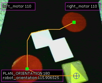
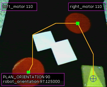
1>as you can see if the yellow target moves a bit away it forms a new path!!! (pic 1 and pic2 where plotted not during two differnt runs, but the same run).
2> the left motor variable seems to be tuck at stop(110). even though the plan, and the angle is moving...
hoping for your reply..
i think the robo file needs a bit tinkering.


program.robo
|
|
|
|
arindam [8 posts] |
18 year
|
|
both the motor variables are stuck at 110...
|
|
|
|
Anonymous |
18 year
|
Rizo,
when we used the Boe-Bot in this tutorial the "stop" value was when both motors are set to 110. Thus the robot is stopped ... the reason it is stopped is due to the lack of the Run button in the Button interface. It needed to be pressed so that a variable valled "interface_run" is set to 1 in order for the VBScript module to maps the path planning results to the motor values. As long as that variable is "" or does not exist the VBScript module will cause the motor values to stop or assign 110 to both.
In the original script your "start" button is instead a "run" button. So in order to get your version to run either change the VBScript module to use interface_start as the variable or change the button module to use interface_run as the variable created when the start button is pressed.
Hope that helps,
STeven.
|
|
|
|
arindam [8 posts] |
18 year
|
|
hey thanks a lot.... just changed the SCRIPT works well now~!!!!!!
|
|
|
|
demo
Anonymous |
18 year
|
|
hey STeven i have tried out quite a few things, including adding a erode module after the negative, but it becomes very clumsy, and the bot while tracking the boundary of the obstacle either collides repeatedly with the obstacle or looses track, if you could take your time and write a code for obstacle avoidance.or change the path planning module some how to track say about (8 cm) away from the zero and non-zero divide. i think it might work better , waiting to hear from you soon
|
|
|
|
Anonymous |
18 year
|
Rizo,
The way that works IS to use the erode module. Perhaps you just need to erode even more (increase the value in the GUI) and see if that helps.
Normally with path planning in robotics you always think about increasing the size of the obstacles to at least 1/2 the diameter of the robot. This ensure that any path planned always has enough space around obstacles to move. Once you've 'dilated' the obstacles (or in your case eroded the free space) the path should be clear.
What happens when you erode even more?
STeven.
|
|