|
Radial distortion coefficient
Jean from Canada [4 posts] |
18 year
|
Hi all
This seam to be a very useful program.
I'm trying to use it with an omni directional vision system.
Basically it's a quickcam pointing to an paraboloidal mirror.
I'm experimenting with the radial distortion module to see if i can accomplish what i need using RoboRealm. However, i cannot find any clear explanation of what are parameters ABCD.
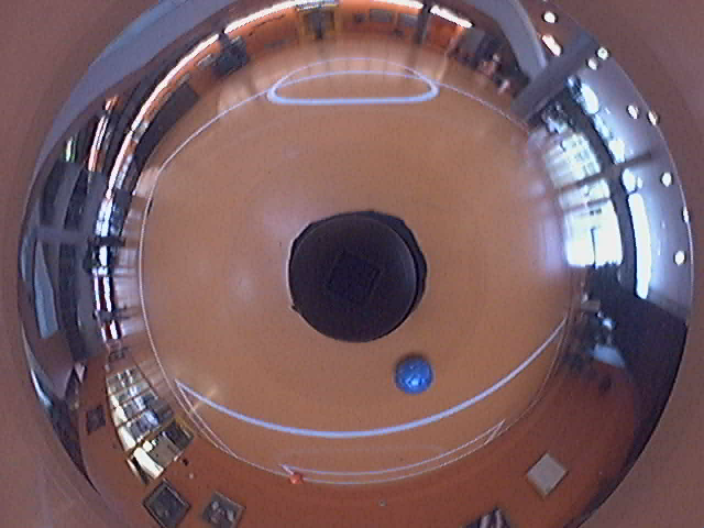
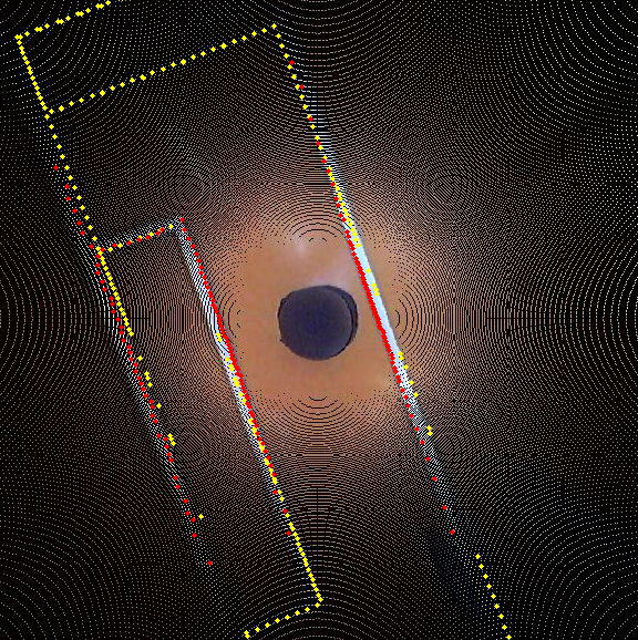
for reference here's the kind of distortion that i try to correct.
It's like a very severe barrel distortion.
The corrected image can be huge, because i have a very wide angle of vision ... so it would be interesting to correct distortion but keep only points inside a certain clipping region.
after correction the point at (x,y) is moved to (X,Y)
h0 = 72;
S0 = -132.9482;
S1 = 0;
S2 = 0.0033356;
S3 = -9.8135e-006;
s4 = 3.1266e-008;
r = sqrt(x^2+y^2);
z = S0 + S1*r + S2*r^2 + S3*r^3 + S4*r^4;
scale = -h0/z;
X = x*scale;
Y = y*scale;

|
|
|
|
Anonymous |
18 year
|
Jean,
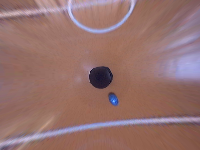
There were a couple of things missing from our Barrel distortion module for it to accept such a wide distortion. Those items have been added and will be included in the next release in a day or so. I assume that the following image

is more or less what you were looking for? The module will now use the values you provided directly.
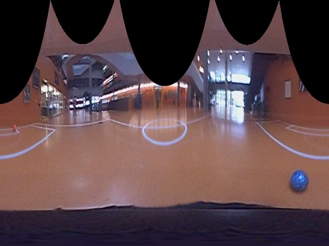
As we were on the subject of image warping we also have added in a polar unwrap that you may find useful for your images too. We at least found it to be a really nice way of understanding the scene the robot is in. I assume it is a basketball court or something similar?

We'd also like to ask permission to use your image as part of the documentation for the polar warp. May we do so?
Look for these items in the next release and hopefully your image as part of the examples for those modules.
Thanks,
STeven.
|
|
|
|
Interesting
Jean from Canada [4 posts] |
18 year
|
Thanks,
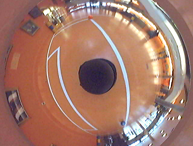
It's nice to see that you where interested enougth to make somoe code out of it. I'm a bit surprised that the straigth line look a bit like a sinus on your image. Because of camera-mirror alignment the center of coordinate is not exactly the center of the image, probably half of the radius[ sqrt(x^2+y^2)] are too big and half is to low wich lead to this shape.
To see if it help:
I have my center at
cx = 325;
cy = 248;
top-left pixel is (1,1)
h0 = 72.5;
--------------------------
To help your user to understand how to get those values:
The S parameters come from a Omnidirectional Calibration toolbox.
http://asl.epfl.ch/~scaramuz/research/Davide_Scaramuzza_files/Research/OcamCalib_Tutorial.htm
The h0 parameter, serve as a scale factor.
Physically it's the vertical distance between the object and the focal point in my mirror. You can get this value by adjusting the scale after you have undistorted know distance. In my case the mirror focal point seam to be about 72 cm from the ground. Once the scale is set ... 1px in the image = 1cm in the real life.
The 'corrected image' need to much reconstruction to be usefull, so i find object in the mirror then correct only the position of object for tracking.
--------------------------
The polar view is very interesting.
We currently use such a view in the working build.
However the colored object we used for self localisation are going away this year. So we question the utility of it foro our need now.
This being said it's a very intuitive vision and it's very helpfull to see vertical things as being vertical, rather than radial.
------------------------------------------
In case you where wondering what i'm working on .. here's some nnice looking image of our self-localisation using white line project. However, in real life we don't have time to process the whole image at 30fps so we do the transformation only on some scan lines.


|
|
|
|
Oh ... yes
Jean from Canada [4 posts] |
18 year
|
Of course, you have my permission for the polar unwarp help file.
The scene is in our university reception/event area.
The field is a strangely scaled half soccer field.
(We are building a team of autonomous soccer playing robots)
Currently we are running real time linux on industrial embeded computer and are wuite struggling to find cpu time to do everything we want to do... so i doubt roboreal will be used as a core.
However it's a very usefull program for developpment of computer vision algorythm and prototyping.
|
|
|
|
Anonymous |
18 year
|
Jean,
thanks for the images! They have been incorporated into the documentation for those modules. No worries about using RR onboard ... if you can get something out of RR for experimentation then that's great. We realize platforms are very varied and certainly understand the need for such.
Also, is there a formal way we can recognize your group? We'd like to add a footnote in those pages indicating where we got the images from. Perhaps your group has a website we can link to?
Thanks,
STeven.
|
|
|
|
Jean from Canada [4 posts] |
18 year
|
Hi Steven ...
I was sure i answered to you last week.
Look like i have'nt sent it.
I am part of the robofoot project
http://robofoot.polymtl.ca/
--------------------------------
On another topic .. i'm really curious on how you did the inverse transform.
In an analytical way, i've found the inverse for second degree polynominal... howeer for the forth order maple output was a page full of .. well unusable information
Is there any numerical aproximation / iterrative method you used ?
I'm also curious about your implementation of ressempling .. do you knwo any good reading on the topic ?
Thanks you a lot !
|
|
|
|
Anonymous |
18 year
|
Jean,
We checked around similar lines as you did for inverse fourth order polynomials and did not find much until we stumbled on the Secant method. The problem was reducing the inverse problem to a single variable (we tried x,y being variable but the inverse would stick in local minimums too easily). We thought we would use the Secant method but eventually did not ... but it did help us with a key thought:
Keep in mind that the radial transform is along a radial line. I.e. the transform mentioned above changes the X,Y coord ALONG A SINGLE LINE radiating from the center of the image. Thus given a Y coordinate as a guess of the original point, you can determine the X coordinate of the guess based on the slope of the projected point (they are the same!). Given this X,Y guess you can then calculate the forward transform to determine how close it is to the destination point. Now you have a linear iterative search process.
Turns out to be quite easy if you use that tidbit and an iterative search. We iterate until the error is <0.01 per pixel which visually speaking works well. Given that the X,Y guess travels along a single radial line it converges quite quickly. Plus keep in mind that you have a lot of symmetry so you really only need to calculate one quadrant and reflect to get the others.
Once you have the inverse mapping things can proceed much quicker from there.
If you need more of a description let us know ...
STeven.
|
|