
Pololu Orangutan SVP
The Pololu Orangutan SVP is an ideal controller for a mid to small sized robot. It provides many of the capabilities one would want on a robot including motors controllers, digital input and output, analog input, 2 line LCD screen and servo (PWM) control. All that functionality also comes at a very reasonable price! The SVP RoboRealm module provides an easy way to interface from your PC to this controller from RoboRealm.The module is meant to allow RoboRealm to communicate with the SVP while connected via USB or bluetooth wireless link. It requires you to download the AVR Studio C application into the SVP board in order to facilitate communication with this module in RoboRealm.
From there you can use the SVP as a servo controller, digital IO, input device, etc. from within RoboRealm by setting or reading the variables set by this module. If you have special requirements you can also modify the C program to do other processing (the link above is to the source code).
Naturally, you can roll your own RoboRealm SVP communication using the Serial module but having a stock module perform this means you can test things out quickly without needed to understand the internal programming of the SVP.
The communication protocol that the module uses to communicate with the SVP is a simplistic packet based protocol. The data transmitted is a 7 bit value with the 8th bit being a sync bit in case the SVP and PC become out of alignment. Only the header bit has the 8th bit set, all other bytes do not. This allows that when a new packet is to be processed that the first and only first byte has bit 8 set.
Values such as the analog signals are also passed back to the PC using the same structure also including a CRC to be sure that the bytes where received in order correctly.
Interface
Instructions
1. Setup - Open the AVR Studio development environment and download this program and upload it to your SVP board. The provided C program is how the communication between the PC and the SVP is accomplished. It is required otherwise the PC will not be able to tell the SVP what settings to make nor be able to read any analog or digital values.
The program can be modified as per your needs but you will need to be careful not to destroy any of the functionality otherwise the RoboRealm module may stop working as expected if it is not getting the right signals back from the SVP.
2. COM Port - Specify the COM port that your SVP is connected to. Note that the SVP comes with a USB cable that simulates a serial port on your PC. The port number for these kinds of virtual ports are normally above the standard 1-4 physical ports. It should be the serial port labeled as "SVP USB Communications".
3. Baud Rate - Specify the baud rate of 115200 to communicate with the SVP. Note that this is much higher than the standard 9600 normally used. The higher rate provides much better responsiveness than the lower rates. If you change the baud rate you will need to do so in the uploaded C application too.
4. Remember As Default - Select the "Remember as Default" checkbox if you would like the current COM setting to be remembered by RoboRealm such that whenever the SVP module is loaded the COM port and BAUD rate will be auto-populated to the current setting. This ability allows you to not have to constantly change the COM port setting when loading in successive RoboRealm robofile configurations.
5. Servos - Once communications are specified and you have a servo hooked up to the board you should be able to move the appropriate slider according to which pin you used in order to see the servo move. Note that you MUST connect PB3 to SA, PB4 to SB, and PC0 to SC in order for the servos to work. Note that the PB3, PB4 and PC0 are across the board over the LCD from the SA, SB, and SC pins. Keep in mind that negative/black is on the outside of the board. If the servo does not move, check your wiring off the servo that the COM port/USB cable are all connected and properly specified.
6. Variables - Select the appropriate variables that contain or will contain the position value that will be sent to the servo board. This is used to automatically change the servo values based on your VBScript (using the SetVariable function) or Plugin based program.
7. Current Value - To manually set the servo position type in the appropriate number (500-2500, 1500 is the default neutral) into the text area or use the slider to adjust the value. The servo position will be updated as appropriate. Note that the current limits of 500 and 2500 will most likely be beyond the capabilities of your servos so you may want to tighten the range.
8. Sliders - You should be able to move your servos by dragging the sliders to the right or left or by specifying a number within the current value text box. If the servos do not move check your USB cable and/or board power connections.
9. Min/Max Limits - You can also use the min/max limits to ensure that even if the variables specify large or low values (due to programming errors) that the board does not actually attempt to move the servos above or below the specified limits. This can be used as an additional precaution in case your servos cannot physically move beyond certain limits.
10. Motors - Two motors can be connected to the M1 and M2 pins to drive DC motors. The motor controls are very similar to the servo controls and also include sliders and min/max limits. Note, however, that the neutral motor value is zero as apposed to 1500 for the servo. See Variable Control for more information on how to programatically move the robot.
11. Analog - If you want to sample the analog values specify a variable or type one in that will contain the value from the appropriate pin. Note that you must select the checkbox next to the Analog Pin in order to activate this functionality. As soon as the pin is activated the value read at that pin will be displayed. Note that even when unattached the pin will show a very low <200 value due to noise. Also note that when pin 0 goes high that other ungrounded pins will also go high due to signal bleed.
Once the value is placed within the variable you can then use this value in other modules, or accessed via the API, extension, etc. in order to move the value outside of the RoboRealm application.
The trimpot is also included in this interface. You can change its value by rotating the pot located right next to the USB connector.
12. Digital Pins - The SVP comes with many digital pins but when all other capabilities are in use 7 digital IO pins remain that can be configured as an input or an output. Unlike Analog pins, Digital pins can only receive a 1 or 0 (on or off) as apposed to a full numeric value. Likewise, a digital pin set to an output can only send an on or off to the pin similar to a switch.
The module provides a way to either receive or send signals to these pins via the C program. Keep in mind that the digital IO pins use inverted logic, they are Low/Off when the checkbox is checked. Also keep in mind that for output you need to connect to the two inner slots (positive and IO) as apposed to IO and ground.
Each pin can either be set as an input or output. Do this by selecting the "in" or "out" radio button next to each pin. If you are specifying a pin as an output selecting the checkbox will then turn that pin high or low. Be sure the enable the pin (first checkbox) to enable the controls for that pin.
For input pins the checkbox will reflect the read high or low state of the pin but will remain disabled.
To automatically send or receive a bit select or type in a variable that will be set if the pin is configured as an input or read into if the pin is configured as an input. Note that you can tell RoboRealm which bit of the variable you want to set/get by using the provided bit dropdown.
As an experiment, you can select the pin D1 as an "out", By checking and un-checking the checkbox you can make the Red LED blink.
If you then select the IMAGE_COUNT variable (which holds the current image counter) as the variable and select Bit 0 the LED will blink for every two frames captured. Selecting successively higher bits will slow the blinking by a factor of 2 for every bit.
13. Buttons - The SVP has 3 physical micro buttons located on the board. If you enable this interface and then press one of those buttons you should see the checkbox change in the GUI interface. This allows you to react to those buttons by saving their state into a RoboRealm variable for later use.
14. Battery - You can keep a check on the battery life of the SVP by enabling the battery checkbox. Adding in a variable will place the current battery power rating into that variable for use by other modules such as the VBScript module. Note the value is in millivolts.
15. Play Song - you can quickly select a song and press play to hear the SVP play a quick melody. To automate the playback of songs select a variable that will contain the song name as seen in the dropdown. Note that after the song begins playing the variable is cleared to avoid repeating the song. To add your own songs you can edit the "Music.rtttl" file in the RoboRealm folder. This file contains RTTTL formatted melodies which are converted and sent to the SVP for playback. Note that the RTTTL format is the Nokia Cell Phone ringtone format and can be found for free in many sites.
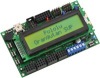
16. LCD - The SVP comes equipped with a 2 line LCD display. The LCD controls in the SVP module provide a way to display text on that screen. The variable dropdown provides a way to send any text to that LCD screen while the Static Text allows you just to type some quick text to see on the screen. Note that if both are specified then the variable will take priority.
When sending a text message the first line will be used and wrap to the second UNLESS you specify a "\n" within the text string which will move to the second line. Remember, you only have 32 total characters so use them wisely!
See Also
Sparkfun Arduino
Axon
Parallax BoeBot
A-WIT BOL-BOT
For more information
Orangutan SVP-324 Robot Controller
| New Post |
| Pololu_Orangutan_SVP Related Forum Posts | Last post | Posts | Views |
| None |