|
Variable Values on VBScript
Vnik from Colombia [13 posts] |
17 year
|
Hello,
I am doing a visual odometry for 3 robots with a camera (determinate the X,Y,theta - position and rotation angle of each robot; I already have the X,Y coordinate; but I don`t know how to determinate the rotation angle of the robot.
I try with the Visual Anchor module but it doesn`t work for me as it tell me the whole image rotation.
Then I have the idea of figure it out the angle with the "Calculae Angle" module. for that I use the "Geometric Statistics" module and the use the change on the Bottom Right X and Bottom Right Y. But as the calculate angle needs 3 points - anyway I would need 2 points to calculate angle from start point - I use VBScript to "save" 3 different values from X and Y, and then use them on "Calculate Angle" module.
I put this code on VBScript, I have 3 IF statements as I need to save 3 times X,Y values Without overwritte them (there are 2 other codes just like this but for the other 2 robots). (but it doesn`t work) I would like to know why.
Or if anyone can please give me an idea of how to determinate the rotation angle of each robot-
red_bit = GetVariable("red_bit")
if "red_bit" = "1" then
GetVariable("BOTTOM_RIGHT_X")
SetVariable "rojo_X1", BOTTOM_RIGHT_X
GetVariable("BOTTOM_RIGHT_Y")
SetVariable "rojo_Y1", BOTTOM_RIGHT_Y
SetVariable "red_bit", 2
else
if "red_bit" = 2 then
GetVariable("BOTTOM_RIGHT_X")
SetVariable "rojo_X2", BOTTOM_RIGHT_X
GetVariable("BOTTOM_RIGHT_Y")
SetVariable "rojo_Y2", BOTTOM_RIGHT_Y
SetVariable "red_bit", 3
else
if "red_bit" = 3 then
GetVariable("BOTTOM_RIGHT_X")
SetVariable "rojo_X3", BOTTOM_RIGHT_X
GetVariable("BOTTOM_RIGHT_Y")
SetVariable "rojo_Y3", BOTTOM_RIGHT_Y
SetVariable "red_bit", 4
else
SetVariable "red_bit", 0
end if
end if
end if
Thanks in advance.
|
|
|
|
Anonymous |
17 year
|
vnik,
Your VBScript is a little incorrect. You want to assign the result of a GetVariable to a variable and then use that variable in the SetVariable. So what you have
GetVariable("BOTTOM_RIGHT_X")
SetVariable "rojo_X1", BOTTOM_RIGHT_X
will *NOT* work but
BOTTOM_RIGHT_X = GetVariable("BOTTOM_RIGHT_X")
SetVariable "rojo_X1", BOTTOM_RIGHT_X
will or in a more abbreviated way
SetVariable "rojo_X1", GetVariable("BOTTOM_RIGHT_X")
will work too.
Are you using a overhead camera or is the camera located on the robot? Just trying to figure out your description ... perhaps if you included an image or two that would help us understand your issue.
STeven.
|
|
|
|
Vnik from Colombia [13 posts] |
17 year
|
STeven,
Thank you for the answer, I actually had that error and correct it this way for the red robot:
red= GetVariable("red_bit")
if red = 1 then
rojoX1 = GetVariable("BOTTOM_RIGHT_X")
rojoY1 = GetVariable("BOTTOM_RIGHT_Y")
SetVariable "red_bit", 2
else
if red = 2 then
rojoX2 = GetVariable("BOTTOM_RIGHT_X")
rojoY2 = GetVariable("BOTTOM_RIGHT_Y")
SetVariable "red_bit", 3
else
rojoX3 = GetVariable("BOTTOM_RIGHT_X")
rojoY3 = GetVariable("BOTTOM_RIGHT_Y")
SetVariable "red_bit", 1
end if
end if
and use the rojoX1, rojoY1, rojoX2, rojoY2, rojoX3, rojoY3 as the input variables on the "Calculate Angle" module, but it returns me unstable and uncorrespondant angles (don't know how to say that word please forgive me)... so I guess I am not doing something well.
I will explain you what I want, for you to understand me:
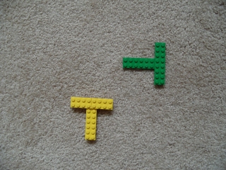
I have 3 robots - segway already locally controled- and want to do visual odometry. each one identified by different colors (see example with bricks on obj.jpg)
The angle I want to calculate is the rotation angle of each robot (please see video: test.avi).
For example, to say: first robot position and orientation: (128,240,90º)
position and oientation after: (128,240,142º)
So I actually want to calculate the third parameter (the rotation angle), for each robot (video only shows one robot, but I guess is just and adjust for each other once I filtered each color).
Thanks in advance.
 segs.zip segs.zip
|
|
|
|
Vnik from Colombia [13 posts] |
17 year
|
|
I forgot to tell you: I have a static overhead camera.
|
|
|
|
Anonymous |
17 year
|
vnik,
Thanks for the images. That helps.
Normally if you need to tell the orientation of an object you would filter out the red brick in obj.jpg and then use the Geometry Module to determine either angle or angle_alt which will tell you the orientation of the robot.
http://www.roborealm.com/help/Geometric_Statistics.php
If you have more than one blob in the image be sure to select "individual blobs" in that interface.
These angle measurements work best when you have an elongated triangle so you might need to add one more brick at the on the front of the robot.
Or if you include an original image (i.e. without the red tracking information) we can send you back an example robofile.
Alternatively, can you send your robofile that you are using and we can better understand how you are using the angles from above. Note that you would need SetVariable statements in order to save the rojo variables for use with the Calculate Angle module. i.e.
SetVariable "rojoX1", rojoX1
STeven.
|
|
|
|
Vnik from Colombia [13 posts] |
17 year
|
STeven,
Thanks again for your answer.
I will add more bricks to robot head as anyway my camera has to be very high - to see the whole area (1.50 meters x1.50 meters).
As the measurement of the X,Y,Theta has to be on Real Time, I think I should not take an image (.jpg) each loop and calculate angle based on that images (.jpg) for each color-robot, because I think it could be very inneficcient; so it's better calculate angle based on current image of camera and previous image of camera. As you are an expert you can guide me if I am wrong.
I am sending you my program, you will see that, have filters for each robot (there are 3) and for each one I calculate the same parameters, naming them different so I can send Xrojo,Yrojo,Thetarojo to red robot; Xazul,Yazul,Thetazul to blue robot... etc.
But the CALCULATE_ANGLE module doesn't give me correct angles, and the numbers change in a weird way, like if robot is moving a lot - what is not happenning because I am doing tests with statical bricks.
 program.robo program.robo
|
|
|
|
Anonymous |
17 year
|
Vnik,
Perhaps you can simply things and just use the ANGLE variable calculated by the Geometric Stats instead of using the bounding points and the COG. You solution will return irregular numbers as the bounding points will change as the object rotates. I.e. the lowest point BOTTOM_LEFT_X will always be the lowest point regardless of when the object rotates ... what you need are 3 points that do NOT change when the object rotates. So the easiest way is to rely on the Geometric Stats module to calculate this.
For example the image

reports the yellow 267 at and the green at 177. Note the really irregular shape used with one side being very much longer than the others .. this provides stability in calculating the angle. We also smooth the shape out quite a bit to ensure a single point exists at the tip. The angle measurement is much more stable using an arrow that ends in a single point. Since your lego blocks do not end in a single point we use the smooth hull to digitally generate an arrowhead.
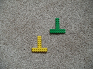
In

the yellow is 91 and the green is 93.So you can see the angle works well. Also note that you don't need the COG module as you have that info from the Geo stats. Also note that we added in a dilate and a blob_size to eliminate any noise objects.
STeven.
program.robo
|
|
|
|
Vnik from Colombia [13 posts] |
17 year
|
STeven,
Thank you a lot for your answer, I really appreciate your help.
I proved the program and at first the angle variable give me crazy data, like for example 120 and suddenly 170, then I "re-build" the robot and put the arrow-head brick larger, that with more satisfactory results, even the angle oscillates.
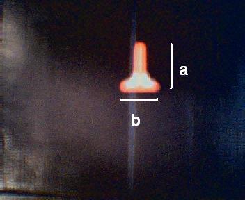
So I will like to ask you if there is a special relation between the distances a, b. I had to build a distance larger than b, so the angle works. (Please see picture redB.jpg).
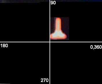
And there`s a way to define that for example always the 90º are in the same place of the image (please see circle.jpg, as I don`t know how to express myself), I ask you this because sometimes I put the brick oriented on the same way, the same place, etc. but It changes the reference, and it`s like "unphased", if the angle on monday gives me 90º, on tuesday it gives me 180... or 270... Can I define like and initialization conditions?
Thank in advance.
 
|
|
|
|
Anonymous |
17 year
|
Vnik,
Yes, there is a very important relationship between a and b. You want a and b to be VERY different for best results. So if a < b that is ok, if a > b that is ok, but a = b is VERY BAD.
Can you paste images here of your trials where the figure is at 90 degree on one day and 180 on anther? As the angle calculate is based on the furthest point in the shape from the COG (center of gravity) the best you can define that point the more stable the result will be. So an ideal shape is

which is not possible using Lego parts which is why we added the smooth hull module previously .. in an attempt to get that furthest point as sharp as possible. (Note the really pointy top of the shape). Be also sure that you are measuring JUST the one object as apposed to the entire image as you have other pixels in the image that could be causing the problem. Be sure to use the Blob_Size or Blob_Filter to remove all other objects but the one that you want to check. This is important to get a single stable measurement.
If you include example images when you see the angle at 90 and then suddenly change to 180 that will help us determine what is going wrong.
STeven.
|
|
|
|
Vnik from Colombia [13 posts] |
16 year
|
Hi STeven,
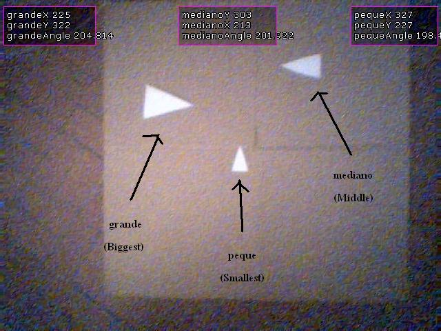
I have change the way I detect robots, this because I had lot of noise due the light, and at my office thats a very difficult issue to change... so I decided to detect each robot by putting them a "hat", each hat is a white triangle with different sizes.
So I do 3 process identically but changing the blob_filter for each triangle:
1. Use RGB_Filter Intensity - as triangles are white is very useful
2. Dilate
3. filter a little more other blobs just in case with blob size
4. Use the respectively Blob Filter for each triangle
5. Geometric Statistics
But again, I want to know the orientation of the robot, so I use the ANGLE variable from Geometric Statistics and the angle doesn't work.
I attached a image.
As you can see on the picture, grandeAngle (Biggest object angle) is VERY similar to medianoAngle (not the biggest but not the smallest object)... and so with pequeAngle... and they are in very different angles.
Is there something I am doing wrong?
THANKS IN ADVANCED

program.robo
|
|
|
|
Anonymous |
16 year
|
Vnik,
Thanks for the image and robofile. The problem is with the COG module. In the way it is setup you are printing the graphical box and coordinates at the time of calculation which is causing the Geometric statistics to be wrong since the box and coordinates are now part of the image. Simply checking the "display as annotation" on the COG module will solve this issue and only print the graphics AFTER all the modules have been executed.
Also, in a successive post you mention 6 objects? There may be a quicker way to get the results for more objects by gathering all the data on all objects and then sorting the results based on the object size. We can help you with that VBScript/Python code if you need help ... please include the source image if that is the case as the image posted here includes the graphics and is perhaps smaller than the one you are using? (We noticed the AREA>500 size check which seems to fail for the smallest object).
STeven.
|
|
|
|
Vnik from Colombia [13 posts] |
16 year
|
STeven,
I actually have to detect 6 objects (3 robots and 3 objects), that's why I'm trying to do and understand all the methods for doing this well.
As you can see I first try to detect 3 robots by colour, then 3 objects by size; but after all this time I have decided: to detect 3 robots by colour, and the 3 objects by shape (I don't need to know objects orientation, only robots orientation are needed). So I don't think more complex code is needed, or what you think?
So I will use the program for detect robots by colour and add shape detection for objects.... I'm hoping it will not become slow as there are more processing stuffs.
I also hope the pixels to centimeters convertion don't have big errors... as well my camera is overhead static but it obviously have some distortion and I don't know how to correct this, I used the caltech's camera calibration toolbox to identify the parameters but I don't know how to use the results.
Anyway I will put those two programs in one (colour + shape) and prove it.
I have a question:
As you can see in the .robo file, I write data on a .txt file; I have a program in matlab that reads this file and save the last 2 data from the file to the plot it and send it via bluetooth.... my question is: I use textread() function to read the file... but I haven't prove RoboRealm + MATLAB running at the same time...
Do you think it would be a problem, i.e when MATLAB will try to read the file and RoboRealm try to write data at the file?
Thank you a lot!!
|
|
|
|
Vnik from Colombia [13 posts] |
16 year
|
STeven,
I forgot to make you another question (apart from the other on my prevoius post).
Is there a way to detect the 3 objects by shape with the blob filter in the same module and have the X,Y coordinates for each one on different variables?,
I ask this because I think it will be more efficiently if the needed of revert the image and make the RGB filter and then the blob filter all this 3 times..... n times... can maybe amke just once.
And because as I already have to put this together with the other 3 robots detection by colours... it is a very large code.
I tried to use the Object1, Object2, Object3.... in the Blob filter but unsucessfull as well didn't figure it out how to save each object coordinate on different variables and I also noticed that only the code that is in the Main is the one that executes, the one in Object1, Object2.... doesn't.
Thanks again.
|
|
|
|
Anonymous |
16 year
|
Vnik,
I would probably use the Matlab API functions to communicate between Matlab and RoboRealm. While writing a text file will work there is a small change that both RR and Matlab will try to access the file at the same time and cause an error. Using the API will prevent this issue from happening and also be much more efficient than writing a text file. See the Matlab sample in
http://www.roborealm.com/downloads/API.zip
which has a matlab example that works quite well.
For the detection of multiple objects in the Blob Filter, yes, just switch on the create BLOBS array checkbox in that interface and an array will be created that contains the COG of all the object. Arrays are a little different than other variables but can also be referenced in other modules using
variable:X
where X is a number from 0 to the size of the generated array.
Or in VB/Python you can use GetArrayVariable to get access to this array.
Also note that Shape_Match module does a similar thing in creating an array of results.
STeven.
|
|