

Comparing Objects
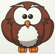
Comparing a sample object to a known object is an effective way of determining if a particular object conforms to a known standard. This tutorial shows how to compare an object to a known standard with subtle changes that indicate a problem. The object is assumed to be planar and moved into view on a conveyor belt system. In our case we are using a printed graphic of an Owl that may be seen on packaging or used as product logo on labels. There are small differences in the graphic that are used to simulate printing faults.
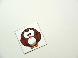
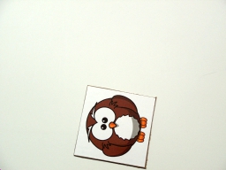
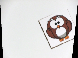
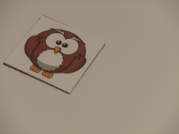
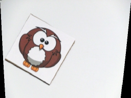
First we start with the ideal template image that we want to compare with successive test images.
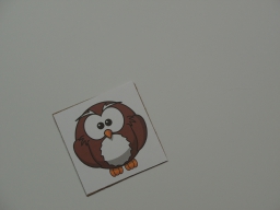
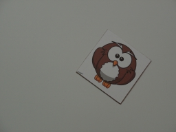
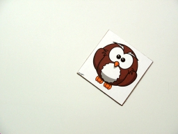
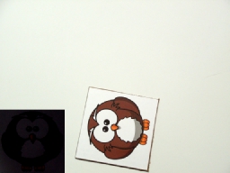
Once we have a good clean copy of the template, we need some example images to test against that are as close as possible to the final production environment where the quality check would be performed. These images are taken with:
- With enough light - Too little light will cause the camera exposure to be long/high. This can cause motion
blur which will soften object edges and can even remove smaller parts of the object entirely. Too much light
will remove color differences or flatten intensity ranges that are important when comparing objects for
intensity changes over the image. Ideal lighting will result in the image being in the middle of the
intensity range of 128 (0-255 for most images) which is the case in the following images. Having the mean at 128
ensures that enough high and low pixel values are captured without causing the CCD sensor to clip intensity values.
- A stable camera mount - This is relevant since you want to be sure that image distortion is the SAME for each
image that you take. Any camera vibrations should also be eliminated since you want to ensure that the object edges are
sharp.
- A uniform lighting solution - Shadows, highlights, etc. are minimized to eliminate any image artifacts during comparison. While the images themselves may not appear very bright the lighting is even throughout the image.
We can now use the Normalize module to ensure that the image pixels occupy the full intensity range and fix our overall intensity range. Some cameras (such as the consumer camera used for this tutorial) will auto-correct lighting variance (high to low range) to a less than ideal range. We can correct for this to some extent in software without sacrificing image quality.
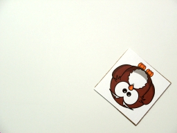
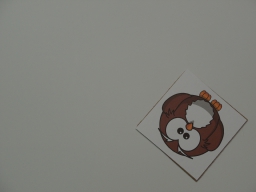
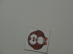
We used 3 small variations in our graphic (eyes, nose and feet). By flipping through all the variations we can see the changes done in the graphic. Those are the variations we are looking for in comparing images.

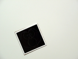
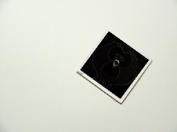
Comparing objects can be done in many ways. The key is to compare two images with each other in a pixel to pixel comparison. Before we can do this we need to ensure that the current image and template image are as close as possible to each other in terms of placement. Our template image was just the pattern to be tested but our example images include a lot of white space and are not necessarily aligned (i.e. rotated) nor the right scale as the template. Thus subtracting the two images from each other to reveal differences without alignment would result in something like:
This bad match shows the template being subtracted from the current image without regard to translation or rotation of the template prior to subtraction. Clearly this isn't what we need.
Instead, the next step is to use the Align Image module to align the template into the current image. The module allows for quite a few options in order to do this which you can experiment with in order to get the right results.
Using this module to rotate, scale and subtract the template from the current image we get a much better result.
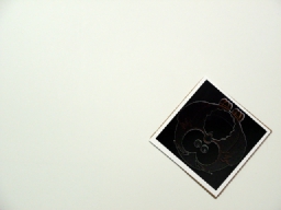
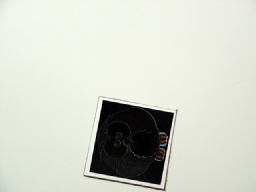
These images show the result of subtracting the template image from the current image after aligning the template with the current image. This will resolve translation, scale and in plane rotation differences between the template and current image. Note, if the current image is taken in such a way as to be very different from the template the "match score" result produced by the Align Image module will be very low. In the images above, the alignment score is about 90% which indicates a good template match was made.
There will always be some noise as taking images from two different camera shots will always differ slightly due to acquisition noise.
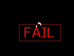
You can already see some residue from the subtractions. Ex #3 and #4 are already indicate larger differences between the template and image. If we get a closeup image of those two you will more clearly see the issues.
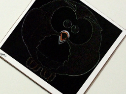
In order to quantify the larger differences (again, some noise will always be present) we run the results through a Grayscale module to eliminate color (note the orange nose) since we are interested only in the magnitude of the image differences. Then a Mean filter module will help to merge areas of large differences together followed by a Threshold module to highlight the difference areas. The threshold level is empirically chosen based on the level of sensitivity to change you need to detect. Using these 3 modules we end up with (zoomed in):
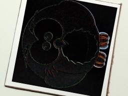
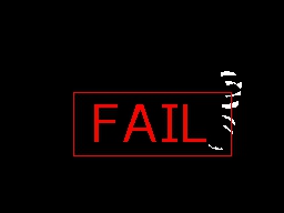
While we can now more clearly understand where the differences are, there is still some fine line differences in Ex #4. These are also present in Ex2. To reduce these edge errors we use the Erode module to eliminate smaller errors.

To remove the background (i.e. white area) we can remove very large objects (remember that RoboRealm sees white blobs as objects). Using the Blob Size module we end up with just the errors in the images.


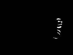
The final images show the differences in Ex3 and Ex4 and can be quantified quite easily by any module that counts the number of on pixels, like the Geometric Statistics. Once measured you can additionally decide how many pixels (i.e. what area) would constitute an error.

What if less than ideal conditions exist? For example, suppose the camera cannot be positioned in a perfectly perpendicular orientation to the object plane as in the above images? For example suppose the following Ex #5 image is more likely to be the image in use. Note the addition of perspective and color distortion in comparison to the above Ex #1 image.

If we run Ex #5 through the current process we end up with a zero confidence as the Align Image module cannot work with perspective transform (i.e. things further away appear smaller). Instead we need a calibration grid to help transform the image into a top down view. We start by placing a printed grid in the same camera view as Ex #5:
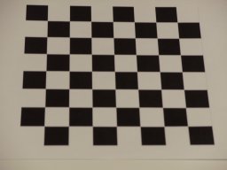
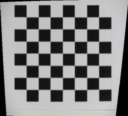
that covers the majority of the work area. We then use the Auto Image Calibration module to transform that image into a nice calibrated sample. One could also use the Perspective module to do a similar transform but the Auto module will do the job for us if a nice grid is in view. Using this module we now get:
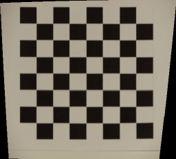
Note that the squares in the bottom of the image are now the same size as those in the top. The black wedges on the side of the image are unknown areas that are created by squeezing the image to fix the aspect ratio of the content of the image.
To fix the color differences, we can use the Color Balance
module in an automatic mode to remove the yellow haze from the image.
Thus, our object #5 after the Normalize module becomes:
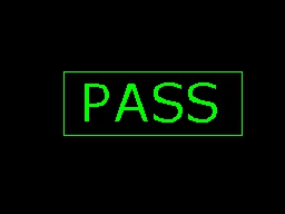
The Align Image module is now able to align the image to 87% accuracy. The resulting threshold image shows no indication of differences ... which is correct. Another example of this correction yielding an 89% match confidence after the calibration process.
You can clearly see how similar the corrected images are to what we used when the camera was perpendicular to the object plane.
While a lot of error correction can be done in software you should try to create the best image possible and then apply corrective modules to get the desired result. The better the input image, the better the results will be.
Now its your turn! Download the zip file to see
all the parts described above. You can also use the Test Images folder in that download to see our database of example images.
The End
That's all folks. We hope you've enjoyed this little adventure into an application of machine vision processing. If you have any questions or comments about this tutorial please feel free to contact us.
Have a nice day!
| New Post |
| Comparing Objects Related Forum Posts | Last post | Posts | Views |
| None |