|
Communicating the presence of a blob to Arduino
Anonymous [6 posts] |
9 year
|
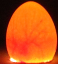
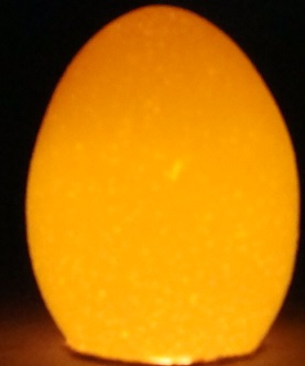
Hi. I am new to RR and so putting my query with great hope. My project is to detect the internal defects in an egg. This can be done when an egg is candled i.e glowing a bulb beneath the egg in a dark environment. One kind of defect in an egg is the presence of bloody spots and veins. One such kind of image is  . Whereas . Whereas  is a picture of an acceptable egg. is a picture of an acceptable egg.
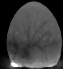
To detect the bloody spots and veins, I have increased intensity and decreased the contrast, after which I have applied median filter to remove noise and then the image is converted into grayscale 
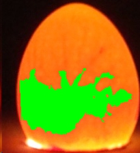
Now I want to convert the bloody area into a blob by converting into binary image (blood area in white, black area for the rest of egg and background). The presence of that blob would then be communicated to my micro controller Arduino mega 2560. It would then, lets say turn on a motor if it finds a bloody egg. I am not sure of what variables we would use to communicate to Arduino
I'd be grateful for any help you may give!
|
|
|
|
Carl from Your Country [1447 posts] |
9 year
|
Zehan,
Attached is a robofile that should help you along the way. The trick is to eliminate any good egg and identify when a red mass is present in a bad egg. This can be done through a couple filters that use color as a main quality to look for that red mass. The other modules help to eliminate the background from the image to just focus on a red mass inside the egg. We detect the mass by the LACK of yellow color ... so the logic is inversed in that we detect good areas and invert that to show the bad area ... but because the background is black we need to use a couple modules to just focus in on the area inside the egg.
Finally the BLOB_SIZE_COUNT variable will either be 0 for no detection or 1 for 1 or more detected areas. This works out great since we can use this variable directly in the Arduino module to transmit a 1 on Pin2 when a bad egg is detected versus a zero when not. You can see how that works in the Arduino module (last module).
As always this simple test case works for the two images you included but you will need at least another 100 if not 500 to really test the system on. As it is color based it is VERY important to keep the lighting the same as when the system is tested. Because the type of bulb will change the color and any additional light will also do the same you cannot have any ambient light introduced into the system ... unless you have a calibrated color somewhere in the image that you can use to adjust the image color with (longer more elaborate technique).
Hope this helps ..
STeven.

 program.robo program.robo
|
|