|
How to set up and relay trigger with time delay
Tomasz from Germany [20 posts] |
13 year
|
Hi,
ok - now that RR has stopped crashing (Thanks Steven!) I'm trying to make my way around.
As a word of defence - I'm completley new to scripting but learning it right now...
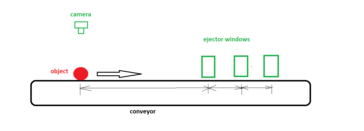
The setup is rather simple - nothing breath taking - an sorting device:
1. Objects will be placed on moving conveyor with constant belt speed.
2. RR should perform basic shape recognition and measure the lenght of the object.
3. Depending on the shape OK / NOK and measurement result one of 6 relays that will control ejectors should be activated (only three shown in sketch but it does not matter).
So the primary condition is shape OK / NOK - I think this could be done with the SHAPE_CONFIDANCE variable: over 65% = OK, less than 65% = NOK
If shape is not recognised -> simply do nothing with relays.
The second condition is the size measurement which can fall into six ranges.
These can be (in mm) 10-40,40-50,50-60,60-80,80-100,100 and more.
The issue I can't really resolve is how to trigger the correct relay based on these two conditions.
I assume that the first (ok/nok) can be combined with the second using some sort of AND fuction in script but how to distinguish the different sizes?
Should I set up 12 variables or just one and compare it to these size ranges?
Second and probably most important issue is to set up either an time delay or encoder to allow the object to arrive at the appreciate ejector window.
The encoder route will be more reliable for sure but this application is not that criticle and I beleive that timed delay will be easier to implement (no idea throgh).
So I can't somehow imagine myself how to trigger the relay at given point in time.
I had an idea to use the COG_Y variable and compare it to image heigth - once the COG_Y =< 1/2 IMAGE HEIGHT the timer should start to run.
After specific time (different for each relay) RR should send signal to Phidgets 888 to fire an relay (again for specific time frame) and after that the time should reset to zero.
Now what is making me worry is what will happen if I'll have more than one object on the screen? Is there's a way to deal with this or should I just set up the maschine in a way that in camera field of view only one object will be visible?
Another issue is what will happen if the first recognized object will require the Relay 6 to fire and directly after another object will require Relay 1 to fire?
I fear that such condition will result in ejecting the incorrect object...
I hope to run the conveyor at 1m/sec. with 13 slots on the belt per 1m.
This will result in about 13 objects / sec.
What are you "feeling" about this? Too fast? Too slow?
I'f I'm to use 15fps camera will such setup work?
Maybe this is my lack of programing knowledge that bothers me here but I cant realy answer these questions myself and I don't wan't to spend money on physical parts (relays, conveyor etc) just to try it out....
I've managed to setup the shape recognition and measuring modules.
Before I spent time writing scripts I'd like to ask you guys what's the best way to trigger these relays?
Do I actually need to set up "time start point" to measure the delay for each frame?
What will happen if I'll have more than one object on screen?

 program_with_data.zip program_with_data.zip
|
|
|
|
Carl from Your Country [1447 posts] |
13 year
|
Tomasz,
All of what you are asking about is possible but its best to focus on one problem at a time. So, first lets figure out the best way to determine which relay should be fired based on the current object in view and then we'll worry about the delay in firing and multiple objects.
Based on your object (a potatoes) I'd not use the Shape Matching feature as what I think you are looking for is a particular roundness of the potato (correct me if I'm wrong on that. Instead I would use the Blob_Filter module with the blob circularity measure to eliminate non-round potatoes.
In addition, you are using a set threshold value. This works, but if the lighting happens to change (or the camera does some weird light adjustment) this will fail. Its best to use the AutoThreshold module for this.
Finally, in terms of sizing, you mention size ranges in mm. I assume this is the diameter of the potato? If the potato is slightly rotated, it can be misclassified (assuming while you are checking for somewhat round potatoes instead of perfectly round). In this case, what you are really interested in is the equivalent diameter of the potato which says more or less the same regardless of any rotation.
Assuming that I'm correct in my assumptions the attached robofile will do this. Note that in order to translate pixels to mm you will have to calibrate the system. I.e. take a ruler and place it within view of the camera and see how many pixels 10cm takes. Then adjust this within the set variable module which has a guessed pixeltomm ratio.
Have a look and see if you understand the attached robofile. If things are about what you want we can move onto the next step.
I would highly recommend getting MANY more pixels in which to test. 3 is well below the noise threshold. 100 would be nice.
STeven.
 program.robo program.robo
|
|
|
|
Tomasz from Germany [20 posts] |
13 year
|
OK - just went through your proposed program.
1. I used the normal threshold module as the lightning will be constant but for now I have only some basic pictures to work with - no physical setup yet. But auto-threshold is also ok. I'm thinking to force camera setup at program start using the Camera Properties module.
2. As for measuring the potatoes size acc. to agricultural standards the correct way to measure an potatoe is by it's smaller diameter therefore I tried to setup two points in my original .robo file and simply measure the distance between.
The reason for that way of measuring is very simple - the maschines to plant new potatoes fields are calibrated to pass through potatoes of given diameter - so the potatoe can be long but not to bulky - it will still pass the i.e. 40x40mm hole...
If I were to use the EQUIV_DIAMETER as base for my measurements I would end up with incorrect values when the potatoe would be long but with small diameter it should fall to "small" ejector port but the EQUIV_DIAMETER will results in much bigger circle diameter based on pixel count.
I've added the same points and measure to your .robo file - the measured value is quite different. The ideal way would be to draw two horizontal lines and measure between them - and this is how I found the HEIGHT variable - thanks to the Geometric Statictics module you used.
3. I tried to use the shape match module to try to eliminate other foreign objects that don't match the "oval" shape - attached are sample pictures of foreign objects typically found on field.
I guess there are many ways to do this but the shape match was the only avaliable module that got tutorial :)
Do you have better solution for that?
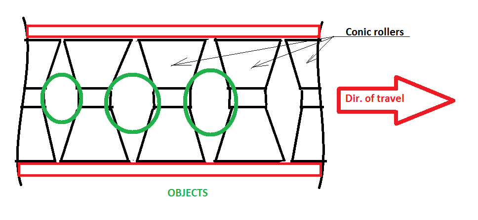
4. The way that the conveyor will be constructed will cause that the potatoes will be centered and set up more or less perpendicular to movement direction and WILL ROTATE to allow 360deg inspection - this is another reason why I tried to simply find most-top and most-bottom point and measure between - see attached sketch.
But it may hapen that there will be two small potatoes in one conveor section - see attached sample image - in such case the maschine should do nothing and let this objects run down the belt where they can be manually sorted by personal.
5. I really like the "Open" module - great tip! I did struggle to seperate and remove unwanted reflections.
Please find attached .zip file with reference photos and two .robo files.
I tried to combine the shape recognition and the HEIGHT variable as it seems to be the most simple way to measure the object height.
I also added Size_X variables to allow easier adjustments in future but I can't make the Relay_X variables to change state to 1.

NOK objects.zip
OK objects.zip
programs.zip
|
|
|
|
Tomasz from Germany [20 posts] |
13 year
|
|
I trying to setup the Blob filter using all variants of circular filter but this is not really working well with oval potatoes at - obviously - they are not cirlcular and return really low weigth.
|
|
|
|
Tomasz from Germany [20 posts] |
13 year
|
I've added some more conditions to see if the potatoe is ok - the color filter to search for yellow (cut potatoe) and green (raw potatoes) pixels.
I've setup some more variables and an IF statement to modify the final variable "potatoeOK".
It seems to work quite well on sample images with only one issue - when the picture shows an wasched potatoe which is also yellow - but this is just calibration that will be done on acutal maschine.
Somehow I still can't change the status of relay to 1 even if the "potatoeOK" is 1.
Can you check what I do wrong?
program.robo
|
|
|
|
Tomasz from Germany [20 posts] |
13 year
|
Now I'm stuck Steven.
Even the original .robo file you wrote is not changing the state of Relay_X variable.
Does this has something to do with releasing memory?
|
|
|
|
Carl from Your Country [1447 posts] |
13 year
|
1. No, nothing to do with releasing memory, everything to do with slight errors in the code.
Note that defining Size_X using the Set_Variable modules does create variables but you still need to
Size_6 = GetVariable("Size_6")
in the VBScript module since VB variables are not RR Variables. The Get and Set functions move that data to and from RR variables. You should imaging the VBScript starting with no knowledge of any variables currently in RR.
2. Based on your previous posts, you are looking for the MINOR_AXIS length ... i.e. if you fit an ellipse to the potato the Minor_Axis is the smaller or thinner part of the ellipse. We have that in the Moment_Statistics module. It is also rotational invariant so does a better job than the HEIGHT.
3. When using the RGBFilter you need to either check for all colors in one module or restore the test image after the module ... the module will affect the image so that subsequent tests will not be valid unless you restore the image data. You can do that with the Marker module. It does this so that you can see how the data is being processed. Without any yellow or green the resulting image will be black, when you feed that black image into the next RGBFilter module ... well, you will NEVER get anything to trigger. Remember, RR is WYSIWYG in terms of image data. If the image is black, then the next module that processes the image will just see black.
Attached is the cleared up robofile. Seems to be working again (save a copy before you modify this!) based on your trials.
Appears that one of the test images does get a shape confidence of 75 ... which is well below the expected 95 so that eliminates that image. Not sure if that number (95) is what you want ... or perhaps add in another template into the shape test that is a bit more elliptical.
I'm still not sure on the shape matching. How would you describe the ideal shape? Perhaps the best measure is that the best fitted rectangle to actual area be a specific ratio? This would eliminate those things that are less elliptical ... or perhaps an area test to a fitted ellipse? More test images would help to make that decision. We can probably add something that would do the trick nicely ... assuming we have enough images to test on.
You will have to download the latest version for this to work. We made a change to the Moments Stats that fixes a problem and works better for you.
STeven.
program.robo
|
|
|
|
Tomasz from Germany [20 posts] |
13 year
|
Thanks for your comments.
I still can't get the Relay_x to change to 1
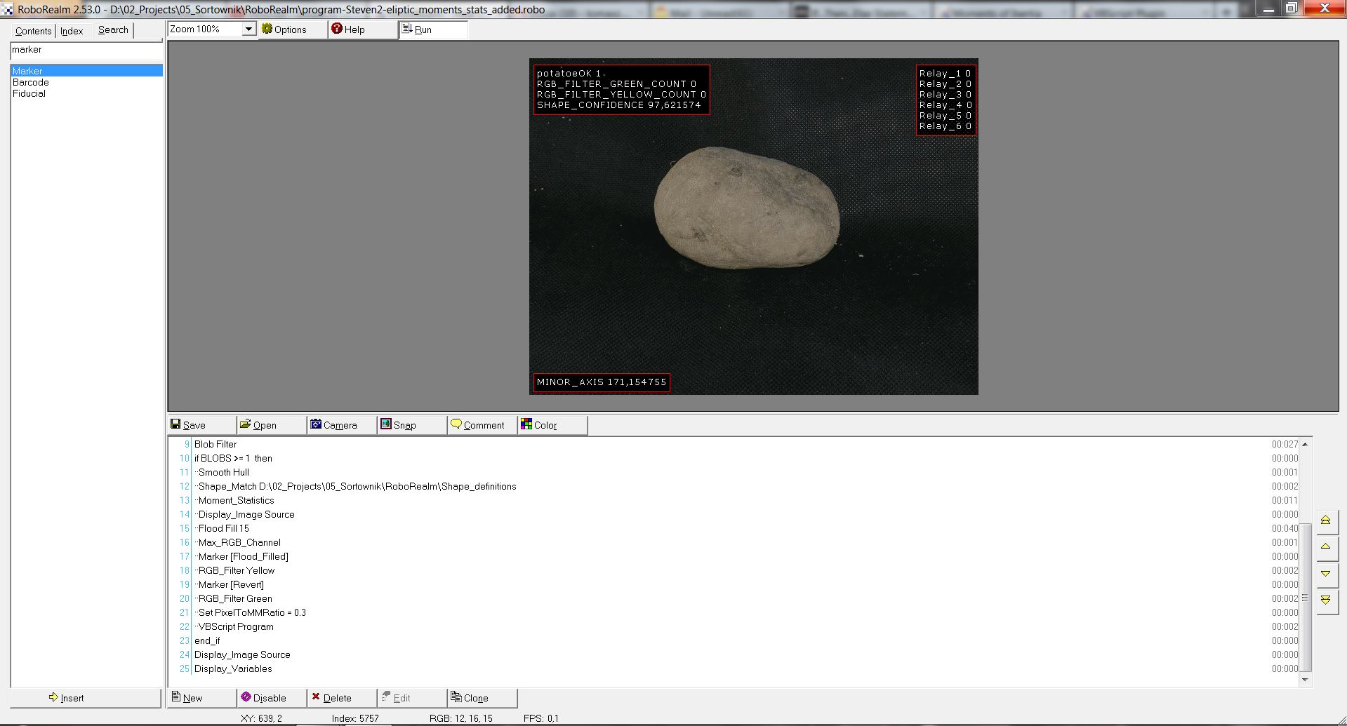
Please see attached screenshoot.

|
|
|
|
Tomasz from Germany [20 posts] |
13 year
|
I've added the SetTimedVariable to controll the delay in firing respective relays and second line for each relay to set it back to zero after 0,5sec.
I hope I got this correct.
Now I'm only left with last two problems:
1. How to define the start point of the count-down for timed variables.
2. How to handle multiple objects in one frame.
PS. As for the issue with being unable to set Relay_X to 1 I'm starting to suspect that there's something not ok with this PC I'm working on.
I've loaded your program and nothing happens (just like in the screen shoot above).
RR did crashed on my PC with "out of memory" errors...
program.robo
|
|
|
|
Carl from Your Country [1447 posts] |
13 year
|
Tomasz,
You have to read my posts.
What is the shape match confidence in that image? Is it above or below 95? What's in the VBScript if statement? What value is it checking for? What did I mention about the 95 confidence value in my last post?
Try more than one image when testing.
STeven.
|
|
|
|
Tomasz from Germany [20 posts] |
13 year
|
Please see the screen shoot I attached - shape confidence was 97,62...
I can even drop it down to 70 it don't help....
I would not be bothering you if I could handle this on my own, realy...
|
|
|
|
Carl from Your Country [1447 posts] |
13 year
|
Yes, that's the problem ... perhaps you don't realize this but in your VBScript you have
isPotatoe = GetVariable("SHAPE_CONFIDENCE")
if isYellow = 0 and isGreen = 0 and isPotatoe >= 95 then
....
so when the confidence is less than 95 which it is in a couple of your test images then NO relay_X will be set.
So, my concern was that this number is not correct and that you should change it to something much less ... perhaps 60.
Does that make sense?
STeven.
|
|
|
|
Tomasz from Germany [20 posts] |
13 year
|
Of course this make sense! It's just I did not managed to get the Relay_X changed even with confidence way above 95 or when I dropped it down to 60 in script...
To be honest I'll try this program on a different PC next week.
I just started with plain pipeline an trying to work with timed variables - and guess what - I can't make them work....
I'm trying just very simple script. No shape matching not nothing.... just size and I can't make this work.
If I use std. SetVariable - cool - works fine. But with SetTimedVariable - nope....
r1 = GetVariable("r1")
r2 = GetVariable("r2")
r3 = GetVariable("r3")
r4 = GetVariable("r4")
r5 = GetVariable("r5")
r6 = GetVariable("r6")
actualsize = GetVariable("MINOR_AXIS")*0.35
if actualSize >= 100 then
SetTimedVariable "r1", 1, 1000
elseif actualSize >= 80 then
SetTimedVariable "r2", 1, 2000
elseif actualSize >= 60 then
SetTimedVariable "r3", 1, 3000
elseif actualSize >= 50 then
SetTimedVariable "r4", 1, 4000
elseif actualSize >= 40 then
SetTimedVariable "r5", 1, 5000
elseif actualSize >= 10 then
SetTimedVariable "r6", 1, 6000
end if
|
|
|
|
Carl from Your Country [1447 posts] |
13 year
|
Tomasz,
I don't think its the PC. I'd not spend any time testing on another PC. If it was the PC, you'd be seeing a lot more issues than just the Relay_X variables. For now, just don't pursue that line of thinking.
The way you expect to use the TimedVariables is not correct. We're not done with step #1 yet so to avoid confusing you I'm not going to address that issue until we are sure we've completed the first step.
What I would suggest you do is record what the results are for the test images you have and decide what needs to change in order to make just those images work. When you feel that you have a good base to work from we can explore the next steps.
I realize this is frustrating and worrying for you ... but we've done this many MANY times and I'm trying to also provide you a good framework in which to best approach this problem. Everything in working with computers needs to be very consistent, methodical and as non-random as possible. One step at a time will get you to your goal.
So, adjust the 95 value in the VBScript down to 60. Then test that script with your 3 test images and see if the relays trigger. If not, try to determine why no. Check every step along the pipeline to ensure that the object is still visible for the next module to process. Check the results of the Blob Filter and the Shape Confidence filter. Use the watch variables module and move that around the pipeline to see when and what those values are. Using this, we can create a script that works and we can then move on from there.
STeven.
|
|
|
|
Tomasz from Germany [20 posts] |
13 year
|
Thank you very much for your patience.
Based on your advice I put together new pipline and script.
The shape confidence is set to 80 - the final value will be adjusted later.
I beleive that I'll need to add more shape definitions to make it more reliabile.
The same goes for RGB filter.
Currently it works well with sample photos and triggers the relay variable as expected.
Only the photos that have some inconsisten lightning and shadows are still somewhat miss-interpreted. I hope to handle this issue by applying better and more consisten lighting in the actual machine.
I also consider using different types of light (UV) to see how they help recognizing damaged or rotten potatoes.
Please see attached .robo file.
I think this is an good starting point.
program.robo
|
|
|
|
Anonymous |
13 year
|
I have made the same type of machine that you ate describing, this one sorted cores by inductance. Although I was not using RoboRealm to do it, it is very close to your application.
This machine was ran by a computer and sorted the cores and placed them on a belt. There are air driven cylinders all along the length of the belt about 12 feet, and on both sides of the belt. As the cores moved the length of the belt, I would turn on the correct valve to kick the part off the belt and into a bin.
I did this program in Visual Basic 6 about 12 years ago, It is relevant to this case as to how it knew where to kick the parts off the belt.
I wrote into the software a routine to create a shift register, this can be implemented in the scripting in RoboRelm. So as it worked in Visual basic, It will work in RoboRelm.
IE., After it knew the graded part value, it was assigned a number of +10 to -10 for a total of 20 places on the belt it would be kicked off at.
So every time it graded and assigned the +/- value to it, it just placed that value in the shift register. As the belt moved it would shift the values in the shift register forward by 1. when the shift register matched the place on the belt that matched the sift register contents, it would move that cylinder to kick the part off.
The problem I see for you using this method is using a timed sequence, as if the belt speed ever varies, everything will end up in the wrong place. I would recommend that
you move the belt incrementally or use some type of encoder to keep track of it.
IE., use a variable to turn on/off the belt, you can then set how fast the sped of the belt is and know how far it moves based on that. Then every time you turn on the belt,
you can increment your shift register. Or, just read the position of the encoder (so many pulses is equal a certain length of belt movement).
once you have this going, you can set some type of timer that checks to see if the contents of the shift register are equal to one of the positions of the cylinder to kick the part off. You may not need a timer for it, as it will be in the vb script and run every time, over and over again by itself.
I hope this helps you out some, and if needed I could discuss this with you further.
Robert
|
|
|
|
Carl from Your Country [1447 posts] |
13 year
|
Tomasz,
Yes, this looks like its working ... at least on the test images that you sent.
Ok, now onto the next two areas. Robert mentioned a very nice way to do this ... ie a shift register or alternatively you can think of it as a time shift. While this is possible, we need to first address the multi-object issue since we need to know very accurately when to trigger the relay.
First, as Robert mentions we MUST have the conveyor move at a steady know pace. Without that we'll miss the potato just about every time. The issue is that while a motor may run very consistently without any load, as soon as you put resistance on the motor it will slow slightly. So when you have 1 or 3 or 4 potatoes on the conveyor the speed will change slightly because of the additional load. So you need to avoid this issue and ensure that the time between the camera seeing the potato and being at Relay_X location MUST be the same time. You need to either use encoders to ensure that the motor increases voltage with increased load, or you need to use stepper motors which have this implicit within them. The issue with Stepper motors is the speed at which you can move the conveyor at.
If you use encoders, you can use the RoboClaw board which allows you to plug the encoder wires right into that board and not have to deal with them any further (if you want to get into PID tuning, you can, but most want to avoid having to deal with that).
Steppers may be a less expensive and easier to work with. We just released the Phidgets Stepper motor driver but there are many others that can do the job. Again, watch the speed of rotation on these.
Assuming that you are not dealing with hardware just yet, lets pretend that the time between the potato and trigger is always the same time based on which Relay we want to activate. You can revisit the above when you are ready for hardware construction.
Now, back to the issue of the timing between the camera seeing the object and relay activation. We NEED to be sure to time the relay trigger when the potato has just based a known position in the camera. I'd recommend using the center as this trigger point. What I mean is that once the potato cross the center vertical of the image, that's when we set the relay trigger so that when the relay does trigger the object should be in the center of whatever you are triggering (not sure if this is a burst of air, a physical hammer, etc.).
There are several ways to do this. The easiest assumes that you have a fast enough fps to catch every object at least once within a small boundary of the center screen. For example, the Blob Filter can be selected to create a Blobs array that includes the COG of the blob (see the blobs array checkbox). We can use that to test against a small part of the center vertical. Something like:
center = getVariable("IMAGE_WIDTH")/2
cogx = getArrayVariable("BLOBS:0")
if cogx>=center and cogx<(center + 20) then
.. set the relay time here
end if
which will ensure that relays are set only when the object is in the center of the screen.
You will note that this technique has a nice side assumption in that multiple objects can be better dealt with. I.e. since we only trigger on the center object, other objects that are not as centered can be ignored. So, in the Blob Filter add in a Location->Horizontal Center with a count of 1. That will remove all other objects but the most centered one. That should take care of most of the multiple objects. If two potatoes have exactly the same X cog then the system would fail so we'd need to understand the frequency of that occurrence. (Again, need more test images).
Now onto the actual setting of the relay. You tried to use SetTimeoutVariable which will get you part of the way there ... the problem is that if you use that function twice the second call will OVERWRITE the first. So if you have two potatoes using the Relay_2 timer, the first setting will be overwritten by the second. If you have a really REALLY short time between the camera image and the actual trigger location then this isn't a problem ... but most likely the timing will require a couple seconds.
Instead, we need to use the AddTimeoutVariable which will create a queue or a time shift register as Robert mentions that will schedule a trigger on a particular relay and not overwrite or change that setting. We can also use this same function to time how long the trigger will fire.
See the attached robofile (adjusted from your version) that includes these techniques. Does all this make sense to you?
Note the new relay timer variables which need to be adjusted in an actual implementation. They should be set to the time it takes to move a potato from the camera center to the actual trigger point. These will be in increasing time, as in Relay_1 is 2 seconds from camera, Relay_2 is 2.5 from camera, etc.
Note that the relays will not NOT trigger unless the object is exactly in the center of the screen. So don't worry if you don't see the relay's be set when they were before. What you now have to test is movement. Ideally you can take a video to work with a play that back.
Because of the lack of test images, this robofile will most likely NOT work for you. So when it doesn't try to figure out why that is. There are a lot of assumptions we have to make that may not be true but we don't know that because we just haven't the opportunity to test this. That's what you will have to do. Take it one module at a time and try to figure out where an assumption we made is broken. Or try to incorporate these changes into something that you do feel is working.
To simulate a conveyor we added a couple modules at the top of the file that should cause the image to shift and look like the images are moving on a conveyor. Note that the object becomes detected in the middle of the image, then only when the potato gets to the border does the actual relay variable trigger. I've left in one image with the robofile so just loading that image should show you this work.
Finally, you will need to download the latest copy of RR for this to work.
STeven.
P.S. don't forget to download the latest RR version otherwise it NOT work.
program.robo
|
|
|
|
Anonymous |
13 year
|
Hi,
I'm aware about the issue with inconsistent motor speed, therefore I'll use an AC motor with built-in incremental encoder.
The other possibility I'm considering is to use simple inductive sensor/switch and place it in front of chain sprocket.
Since the required max rpm at geardrive output shaft is 80 and I plant to use and 20 theeth sprocket I'll endup with 160 pulses per minute at most.
Currently I'm trying to figure out with Phidgets guys if this 888 board can handle this input.
IF NOT - I was hoping to use their USB encoder board to handle this signal from motor encoder. Can RR support this equipment?
(http://www.phidgets.com/products.php?category=7&product_id=1057_2)
I imagine myself that to include this variable in our program one easy way would be to shift the position of the if cogx>=center
center = getVariable("IMAGE_WIDTH")/2 + SpeedChangeVariable
where the SpeedChangeVariable should reflect the actual count of pulses per minute (with some factor applied so that the number will not exceed the picture size). Is this the way to go?
I'll try to add Random number generator to simulate this scenario.
|
|
|
|
Tomasz from Germany [20 posts] |
13 year
|
The only thing I can't really understand is why you use the "added_to_trigger_queue" variable - I can't really get it what it's for.
Your program works extremely well! Thanks! :)
|
|
|
|
Carl from Your Country [1447 posts] |
13 year
|
The problem with using an image is that you need to define a precise trigger point only once. I.e. in our case, the potato can be within that trigger zone for quite a few frames. So in order to not reexecute the AddTimedVariable and add 100's of timing sequences to the queue during that period where the potato moves through the center of the image we use a "added_to_trigger_queue" variable to let us know that we just added it to the queue and not to do so until we zero that out. This is a latch condition. Do something once, wait till it resets (i.e. the object moved out of center image) and then allow it to be set again. This ensures that we only have one timed entry per object and keeps things tidy.
Per your earlier post, yes you can move that trigger point around the image as needed. Keep in mind that you will need to change both the VBScript AND the blob filter as the blob filter will eliminate all but the most centered objects. If you don't change both, the potato will probably not be detected correctly as the overlap of the two conditions will be null.
STeven.
|
|
|
|
Tomasz from Germany [20 posts] |
13 year
|
Thanks for clarification. I need to educate myself a little more....
About the shifting of the center point - I was thinking about doing it in "real time" based on the encoder input therefore if I must adjust the Blob Filter this probably won't work.
I'll try to find some more info about adding encoder input into script on this forum.
If I'll fail to get it right I'll report back.
Tomasz.
|
|
|
|
Tomasz from Germany [20 posts] |
13 year
|
Hi,
currently now I'm in the process of selecting components to build the PC to use the program you wrote for me.
According to RR the time to process the image is floating between 0 and 1 which would mean somewhere under 16ms if I understood the manual correctly.
Since this is an overkill I'm planning to scale down the actual PC used in this maschine for costing reasons.
My question is - do I need more CPU or GPU power?
Actually I was looking to build the system based on the new Intel NUC boards due to it's small dimensions. The board can be equipped even with i3 or i5 series CPU - this should be more than enough for my application.
Do you agree?
Cheers.
Tomasz
|
|
|
|
Carl from Your Country [1447 posts] |
13 year
|
Tomasz,
As more CPU's are more common than GPU's RoboRealm is geared to multiple CPU's as apposed to GPU's. So, purchase a machine with really good CPU and very low graphics and that will work out better for cost/functionality price range. Our local MicroCenter had a special for an i7 with a really bad graphics card for $600 ... and it runs RoboRealm wonderfully!
The i3 or i5 you mention should do just fine. The first mobile machine we ran RR on was a 386 biscuit board doing simple color detection which worked ok. An i3 or i5 should work really well for what you are doing.
Note, that also goes for memory. Unless you are using a really large image 2gig memory will work just fine. Most of that is just to support the OS, RR itself will not use that much based on the filters you are using. 1 gig is also possible but you'd really want to run a trimmed down OS like XP instead of Win7 if you go below 1 gig.
STeven.
|
|
|
|
Tomasz from Germany [20 posts] |
13 year
|
|
|