|
AVM Navigator Module Inaccurate?
Subbu from United States [21 posts] |
14 year
|
I am trying to track a simple pendulum using the AVM navigator module. However, when I use the Learn from motion option, the pendulum is not tracked perfectly. I use the following modules in the pipeline :
OpenNI_Kinect (Depth Image)
Canny Edge
Background_Removal
AVM_Navigator
So please suggest me if I can improve this in any way. Thanks in advance.
|
|
|
|
EDV [328 posts] |
14 year
|
I think that "Canny Edge" module is not wanted here because AVM algorithm needs in textured objects and it possible that AVM Navigator is not suitable for this task.
But it would be good if you could shoot video that demonstrate your problem and it would help us to analyze this situation.
|
|
|
|
EDV [328 posts] |
14 year
|
I used my head as pendulum and it was working pretty well with helping of AVM tracking:
http://www.youtube.com/watch?v=nEcW8zzH7R4
What if you could place some face photo to your pendulum?
It would be funny ;-)
|
|
|
|
Subbu from United States [21 posts] |
14 year
|
Thanks EDV for the prompt response. I have linked 2 videos one with the canny algorithm and one with just the RGB camera from ASUS Xtion Pro Live. As you can see the pendulum is not being detected completely and it is detected only if it comes to the highlighted frame in both the cases.
Well I wanted this algorithm to track the pendulum completely along its path as the pendulum was learned and trained using the Learn From Motion Feature. I am also worried as there are a lot more unwanted "New Objects" that are being recognized without learning them. Kindly help.
Pendulum with Xtion Pro Live RGB Camera :
http://youtu.be/VsqgySuJ98U
Canny Edge Detected Version :
http://youtu.be/7YgTdLNsfJs
|
|
|
|
EDV [328 posts] |
14 year
|
>> I am also worried as there are a lot more unwanted "New Objects" that are being recognized without learning them.
The "Object" is automatic name that assign to objects that were learned from motion.
Just switch off "Learn from motion" checkbox and clear AVM tree by pressing of "Set key image size (New)" button. Further print the marker image that could occupy all interest area during learning (red rectangle that appears after "Learn object" button was pressed). Fix the marker on your pendulum and let AVM Navigator recognize it with disabled "Learn from motion" option like in this video:
http://www.youtube.com/watch?v=ueqDhuHiR-E
The AVM algorithm use only grayscale matching and it not allow to AVM see difference between green and red balls for example. So, good object for recognition with AVM should has appreciable texture. Also you should endeavor so that the object occupies as much as possible the square of interest area (red rectangle) during training because for AVM anything that was placed in interest area will become as object (background also).

|
|
|
|
Subbu from United States [21 posts] |
14 year
|
Thanks for the reply EDV. Well I tried with the method that you told by just marking the bob of the pendulum and getting the center marker to be on the middle of the pendulum. And I also unchecked the learning from motion option. The results did improve to a good extent.
But there were few occasions where the pendulum bob was outside the boxed area of the module. These occurred when the pendulum was on the two extreme ends. But the pendulum was in the field of view of the camera all the time. So by any chance this algorithm could be made to cover the left out areas as well?
|
|
|
|
EDV [328 posts] |
14 year
|
What if you will try to make additional learning of your marker on the pendulum when it is on the two extreme ends?
You can make additional training of object on the same object several times in anytime and you should just press "Learn object" button and further choose the same object from dropdown list in the "Enter object name" dialog window.
So, fix your pendulum in one of extreme ends and make additional training on the marker and further repeat the same procedure for other extreme end of pendulum marker.
|
|
|
|
Subbu from United States [21 posts] |
14 year
|
|
Thanks a lot for the idea EDV, that really makes a good sense and I will try that and update you.
|
|
|
|
Anonymous |
14 year
|
Subbu,
Your video seems to indicate that the end of the pendulum is of red color? Is that true? If so, a simple moving color detector would probably do the job too. Not sure if you can modify the environment or not.
STeven.
|
|
|
|
Subbu from United States [21 posts] |
14 year
|
Hi Steven, well the pendulum end will be tested with a red color bob, a black color bob and a gray color bob. I can modify the environment with changes to background.
I did try out to learn the object at different positions as EDV mentioned, though the results improved, I was not able to get a perfect object tracking. Hence I request you to provide me some more insight into this. The latest video is at :
http://youtu.be/bARDSW6c4cQ
|
|
|
|
EDV [328 posts] |
14 year
|
This video ( http://youtu.be/bARDSW6c4cQ ) showed that all was working well until 0:07 where you have shoved pendulum sharply. Further strong motion blur effect that was caused by high-speed object motion has distorted (smoothed) image of pendulum object and it impeded to recognition.
If you could look video after 0:07 you would see flashings of cyan rectangle (it is additional training of AVM on the tracking object). So if you could increase speed of pendulum progressively then AVM would be able to learn the object (pendulum's bob) during long time and it could improve recognition of pendulum as object.
Also you could paint your pendulum bob to red color and choose “Contents\Examples\Red Object Tracking” from RoboRealm dialog window.
|
|
|
|
Subbu from United States [21 posts] |
14 year
|
I will surely try the steady increase in the speed EDV. The red Object Tracking looks promising as it gives x and y axis values. However, I need even the Z axis
value (Depth Value) to carry on further with my project. Is there anyway I could do this?
I also get an error when I try to run the Red Object Tracking module which says :
Could Not initialize on Port COM2 Speed 2400 (Error -1)!
|
|
|
|
Subbu from United States [21 posts] |
14 year
|
|
And one more thing is that I am not able to run this module with Xtion Pro Live Camera. I can only use this with my laptop web camera.
|
|
|
|
Anonymous |
14 year
|
Subbu,
Couple things:
1. What resolution are you using? 640x480? Can you switch that down to 320x240? That will surely reduce processing requirements by 4x and keep the fps really high.
2. The red object tracking example error you are getting is because that is configured to try to access the Parallax SSC. Just delete that last module since you do not need that. The main module is the RGB_Filter which you can just select and start playing with you webcam.
3. We've not tried the RGB camera on the Xtion since the model we have (early release) did not have an RGB camera. We will see if we can test the system with the latest model ... but that will take a bit to get to us.
4. To avoid blur be sure to DISABLE any autofocus and increase the shutter speed. AutoFocus is just really bad when it comes to image processing. We encounter that issue often ... Increasing the shutter speed WILL dim the image but it will create a sharper image. The AVM module is capable of still working with dimmer images since the content is still there and will be less blurry. You can also use something like the Color Balance module to bring the image back to human preferred lighting levels ... although that is really only needed for viewing. The AVM module should work just fine.
5. Are you seeing the depth image from the OpenNI module like the NI Simple Read? I think there is an assumption that we are making here that you are not seeing. The depth map should be accessible in terms of showing you different colors/etc. This is the information that the Simple Read shows. Are you not seeing that?
Be sure that you have Grayscale selected in the OpenNI module. Then intensity level = depth from camera.
STeven.
|
|
|
|
Subbu from United States [21 posts] |
14 year
|
Thanks for the reply Steven.
For the point number 5 above, yes as you said I am not able to see the depth image in this case because the sample code reads the frames from the depth generator and hence prints the depth value of the middle pixel. So I guess since I cant get this info directly, I will try to look for alternatives. Thanks
|
|
|
|
Anonymous |
14 year
|
I conducted the Experiments as per the discussions above and I want to share few things :
1.) Reducing the size to 320 X 240 did increase the frame rate. So the frame rate has moved up to 27-28 on my dual core so I am pretty sure with the core i7 laptop I will be able to get 30 FPS positively.
2.) I tried to increase the speed of the movement of the pendulum in a relative manner as EDV had suggested before and now the tracking is much more precise.
Thanks for the responses. However the final hurdle is that the Depth data issue still needs to be figured out. I will try the Sample color module and the Red color Tracking example to see if I can get something. However, I would appreciate if I could get some more inputs from RR's end too. Thanks
|
|
|
|
Subbu from United States [21 posts] |
13 year
|
Hi Steven, Well I have reached the point in the project where I cannot further move without getting the Depth Information. RR cannot be used if I cant get the depth data. Hence here are my following requests to you :
1.) Is it possible to add a feature to get the real time depth information of the tracked object from the AVM Navigation module ? OR
2.) Can you please add a feature to get the depth value of the center pixel and write its value to a file in the openni_Kinect module?
|
|
|
|
Anonymous |
13 year
|
Subbu,
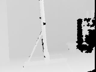
We will let EDV respond to #1. As for #2, that already exsits ... it is just we've not effectively communicated to you how to get at that information. So let us start from step #1. Can you post a depth map image that you see from the Asus to this forum? We will use that image to show you how to get that depth information.
It should look something like the attached. Naturally the content will be different but it should look like a grayscale image with closer objects being brighter. Are you able to see this type of image?
STeven.

|
|
|
|
Subbu from United States [21 posts] |
13 year
|
Hello Steven, Please find the test depth image attached.
Thanks,
Subbu

|
|
|
|
Anonymous |
13 year
|
Ok, that's good!
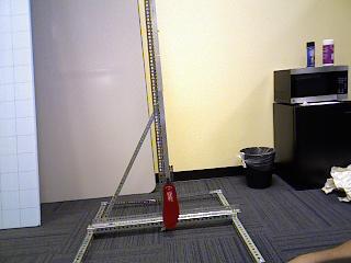
Now, if you notice, the center of that image is nowhere near where your swinging pendulum is ... so in fact what you do NOT want is the depth value at the center of the image ... what you need is the depth value at the center of the pendulum .. correct?
So, in order to do that you will need to first localize the pendulum in RGB space using either red object or AVM.
Can you include the RGB counterpart of that depth image? Or if you do not have that in the same position can you retake a depth map and an RGB image of the same scene?
We can then show how you use one to determine sample position on the other.
STeven.
|
|
|
|
Subbu from United States [21 posts] |
13 year
|
Hi Steven, I have attached the images below.
But I wanted to clear one point that in the experiment, I am required to monitor the constantly changing depth values of the pendulum.
And I will also be changing the direction in the second phase where the pendulum comes near or away from the camera.
Hence I need to constantly take the depth values and save it in a file to do further calculations. And thats the reason why I am still in doubt as the manual calculation becomes too tedious process and may not solve my problem.
So I am pressing hard for requesting a new feature addition.
Thanks,
Subbu
 
|
|
|
|
Subbu from United States [21 posts] |
13 year
|
So how do I calculate the depth value ?
Any chance with addition of new feature Steven?
Thanks,
Subbu
|
|
|
|
Anonymous |
13 year
|
Again, no new feature required.
Try the attached. It should detect the red object and show the distance to that object assuming the Xtion is running correctly.
You may need to review each module (click on each module) in order to see if everything is configured correctly.
Also be sure that the Xtion is producing RAW 12 bit depth numbers which will be the most accurate.
Also note that the distance calculation is based on the information in the following thread which my be a bit different from your implementation.
http://www.roborealm.com/forum/index.php?thread_id=3865#2
Please note that you DO need the latest copy of RR in order for the rectangle (i.e. the area that is sampled for depth) to work.
STeven.
 program.robo program.robo
|
|
|
|
Subbu from United States [21 posts] |
13 year
|
Thanks for the reply Steven. Well when I move the object closer, the depth increases and when I move farther the depth decreases.
And one more thing is the depth distance in millimeters or centimeters?
Thanks,
Subbu
|
|
|
|
Anonymous |
13 year
|
|
|