|
Newbie question
Bram from Belgium [5 posts] |
14 year
|
Hello all,
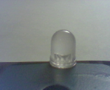
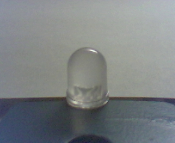
I am currently trying to build a led pick and place machine, but in order to place the leds correctly I need to know how the led is positioned in the feeder. Attached are the 2 possibilities, is this something robo realm can do? If so how would I start on this, I am new to the vision part of cnc. Also, I would need a output pulse (1) on the lpt port pin2 if it is correct, and a pulse (1) on pin 3 if it is not correct. But it has to be either one of them. I guess I first have to detect motion as the led moves in front of the camera, and then see if it matches the correct way, if not then mark it as bad, so that only correct positioned leds are placed on the pcb.
Hope someone can point me in the right direction.
regards,
Bram
 
|
|
|
|
Anonymous |
14 year
|
Bram,
Yes, seems like this should be possible. We are assuming that the position of the LED is what makes it pass/fail?
Attached is an example of how you would test for pass fail position and send the appropriate pin signal on the parallel port.
Note that we are detecting the position of the LED by using an edge detector, cropping to eliminate all but the led and then the COG in order to tell the X position of the LED.
Give it a try and let us know if this is what you were looking for...
STeven.
 program.robo program.robo
|
|
|
|
Bram from Belgium [5 posts] |
14 year
|
Hi STeven,
Thanks for the reply, but in fact it is the way the led passes on the conveyer rail that makes it pas of fail, a LED has a cathode and a anode, and I need to be sure that the leds pass correctly on the conveyer belt type of transport system before they are picked up and placed on the pcb.
The leds pass at about 2 pcs per second, if this is too fast, we could slow it down to about, but not less than 1 led every 1,4 seconds.
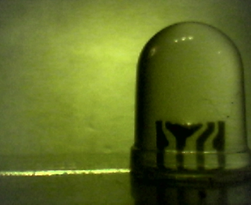
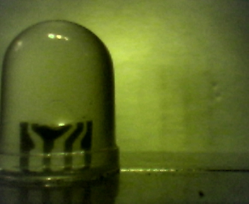
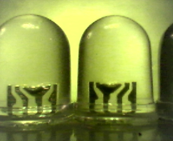
Normally we would check on the length of the legs, but this batch of leds came with the legs pre cut to the length we need, so if you look closely to the 2 images you can see that the filament of the leds is in different directions, it is very subtle but it can be seen, so I was hoping to automate this process, we have to place about 300 000 of these leds.
Kind regards,
Bram

|
|
|
|
Anonymous |
14 year
|
Bram,
Ok, thanks for the description. Before we investigate further are you able to put a light behind the led to help bring out the filament with more contrast? I.e. place a light just below the table facing the camera with the led between the camera and light. This should cause non-filament areas to allow light through and show the dark filament with much sharper detail.
Thanks,
STeven.
|
|
|
|
Bram from Belgium [5 posts] |
14 year
|
STeven,
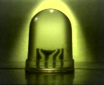
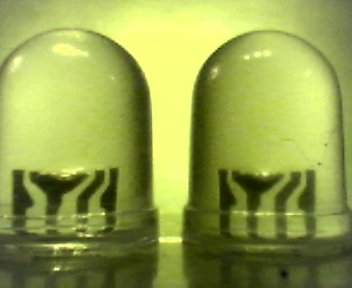
I have been experimenting with back lighting, the problem with these leds is that they are diffuse, so putting a light directly behind it would just give one bright spot, and you cannot see anything anymore. But what I found to be working quite well is projecting light on the background wall, attached is the result. Is this something you think might do the trick?
Regards,
Bram

|
|
|
|
Anonymous |
14 year
|
Bram,
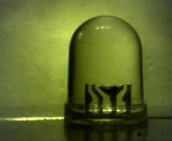
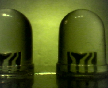
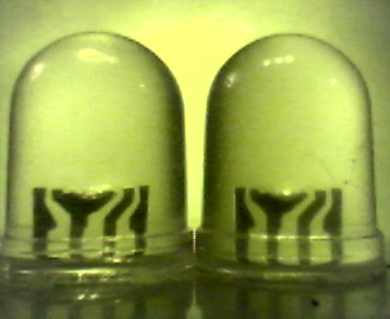
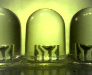
That's perfect!! We already have about 3 or 4 ideas on techniques that will do the job but they would only be known to work on this image. Can you take a couple more shots (at least 5) of other LEDs that are correct, incorrect and approaching the background light/center screen. The approach images are needed to ensure that the system knows when to react to the analysis, i.e. if an LED causes a strange match before it is in the center of the screen fully in front of the back light we want to be sure to ignore that case.
Nice job!
STeven.
|
|
|
|
Bram from Belgium [5 posts] |
14 year
|
Hi STeven,
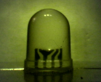
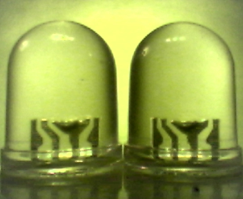
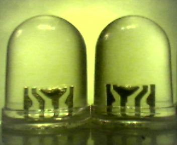
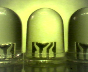
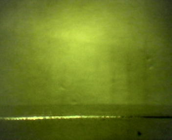
I did some more testing, the results are attached. my webcam tries to auto balance the white levels, and therefore the results are quite different if one led passes or 2 leds pass. Maybe I have to get myself a new camera, what are your thoughts?
Problem is I cannot know when the next led is going to pass. The leds are vibrated onto this conveyer system, it could be that there is a space between them, but it can also be that they are right next to each other.
Regards,
Bram
             
|
|
|
|
Anonymous |
14 year
|
Bram,
Attached is a robofile that does the trick on the above images.
Basically it uses the curvature of the top of the LED to position a box around the filaments and then checks to see where the largest filament is (right or left) to produce the final result.
Note that the robofile only checks for one led and only does so if it is in the middle of the image.
The next step would be to understand how the led will be picked and if you need the visual image to help with that picking ... i.e. you can configure the analysis to only occur when the led is exactly in the middle of the image which would assume it would be picked in that location. If you can describe more how you expect to achieve the picking we can recommend a setting that will best work this that technique.
Also note that this is most likely not the final setup that you will use there may be customization that will be required on the final setup as this robofile assumes the same size of LEDs are used (and distance from camera) but will adapt if the table is higher or lower as the cropping is based from the top of the LED.
Also ... as always, more testing the better!
STeven.
program.robo
|
|
|
|
Anonymous |
14 year
|
Oh, and be sure to download the latest copy of RR as we used some of the latest features in that robofile ...
STeven.
|
|
|
|
Bram from Belgium [5 posts] |
14 year
|
Hello Steven,
Sorry for this late reply. It looks amazing, when a led is pushed in front of the camera and stops, it works perfect. When they move at a constant speed, then I get the strangest results unless the speed is very slow. Now I have been working on a system that moves the led in front of the camera, stops and sends a signal to the pc via lpt, and then waits for a pass or fail, then moves the next led in front of the camera. This way I think I can reach higher speeds. As I said before, I must get an average of 1 led per second to feed the pick and place machine. I haven’t perfected the mechanism yet, and am still working on it, I will show the results, hopefully by the end of the week.
The next stage in the chain is to check if the led is actually working, this is done on the next station, there the led is pressed against copper contacts, a current is applied and if the led works it will lit. This is done 3 times for every color R G and B. now we do this on 3 different stations with a photo transistor to check if it is lit or not, maybe later I could do this also with a webcam and check for the 3 colors at once.
Only when the led has passed all the previous checks it is picked up and placed on the pcb.
Kind regards,
Bram
|
|
|
|
Anonymous |
14 year
|
Bram,
Most likely the reason for the irregular results from the moving led is due to the lack of lighting and thus a slight blurring that is created when the led is moving. This can be solved in two ways, 1) increase the lighting of the entire scene as this will decrease the CCD timing in the camera you are using and take quicker images or 2) get a camera that is more sensitive to low light situations and can take very fast images even in low light.
In fact their also might be a 3rd option that you can try with your current camera. Try using the Options Button->Video tab and select the source or format buttons that come up and look around for the ability to disable auto adjustments like for the shutter. Set this very high so the image will come in really really dark but will take a very quick image. Then try using the Color_balance module with auto intensity or Align_Image module with only the current image selected (leave the second dropdown box empty) as these will attempt to fix the lighting in the image. Sometimes this works, sometimes not. Regardless, the trick is to get the camera to take very quick snapshots without waiting for enough light to fill the CCDs in the camera and then adjust the image afterwards.
At any rate, the blurring of the image while moving is the most likely suspect.
STeven.
|
|