
Lego PC Bot
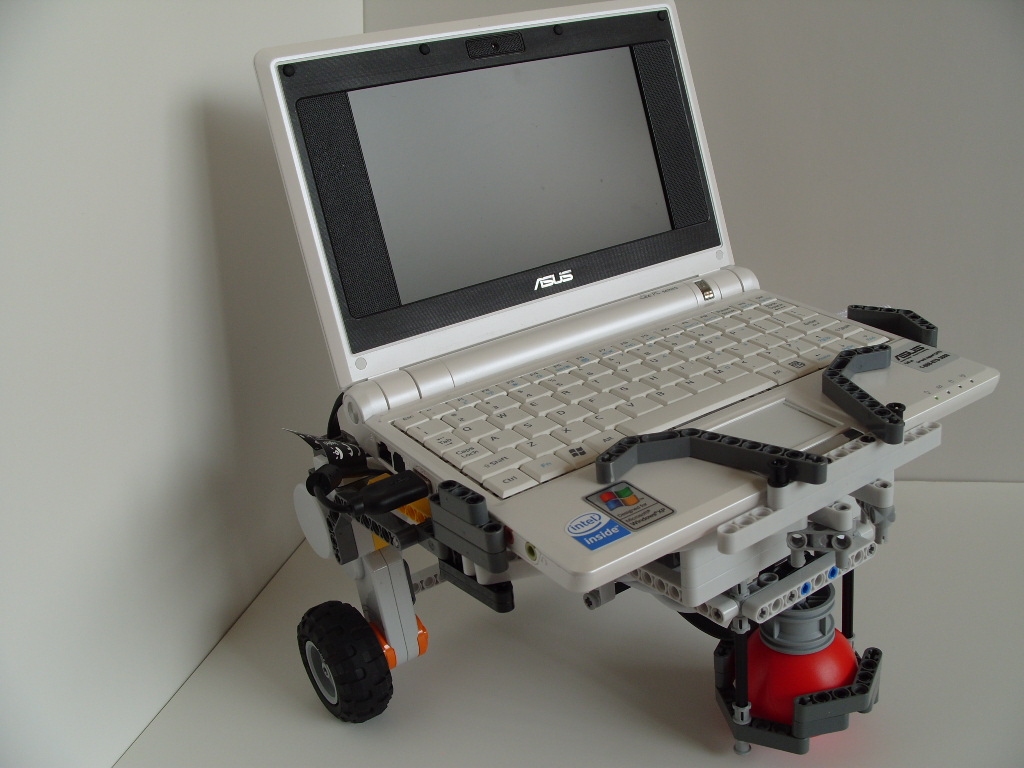
The following tutorial shows the implementation of a PC robot constructed from a Lego NXT kit in order to create an onboard vision processing system. This platform is then capable of roaming around the home environment using the Floor Finder obstacle avoidance technique described in the Obstacle Avoidance tutorial.The parts used in this construction are:
1. Lego NXT kit with USB cable ~ $250.00
2. Logitech camera ~ $100.00
3. Asus Eee Ultra Low Cost PC ~ $350.00
The total cost of the platform comes to $700.00. With some price shopping and camera substitutions that cost can be reduced by about $100.00.
click on image for larger view
Construction
The Lego NXT kit while very flexible is not the strongest construction material to use when creating a robot to hold significant wieght. Thus the choice of the Asus Eee is largely based on weight. There are some other models of PC based robots constructed using the NXT kit that can be seen in at the following sites:
 Mindstorm NXT + Eee PC = Good Times - A robot using the NXT as only an interface from the motor�s/sensors to the Eee PC using RoboRealm.
 BB Vision Platform V1
Mounting a laptop ontop of a Lego robot using a USB camera and RoboRealm!
BB Vision Platform V1
Mounting a laptop ontop of a Lego robot using a USB camera and RoboRealm!
 Lego Mindstorm carrying Acer Aspire
An assembled structure to use as testbed for researching work.
Lego Mindstorm carrying Acer Aspire
An assembled structure to use as testbed for researching work.
Which are equally as good and can be used as additional inspiration during your
construction.
Some of our requirements while building this robot were:
1. The robot must be built with only one kit's components.
2. No additional parts outside of the kit are to be used in platform construction (besides the Asus and Camera).
3. The laptop screen should be open and visible when in operation.
4. The keyboard should be able to still be used when in operation.
5. The laptop should be able to receive wall power without requiring removal of the laptop.
6. Switching batteries for the NXT should not be an involved process.
7. The camera should be attached to the front of the robot looking towards the ground.
In addition we also wanted to not introduce too much weight so that the robot would still allowed the robot to run over apartment thick carpet to ensure home use.
The most difficult process during construction was to ensure stability of the NXT system. Since a wide base (relative to the NXT) was require in order to hold the laptop the robot construction is inherinately unstable and has a lot of "give" within the structure. After many hours of stabilizing and suring of the construction the system runs reasonably well but will tend to disintegrate in various places if the robot hits an unintended obstacle. Thus, while the platform is a great experimentation platform, it is by no means capable of running for extended periods without requiring some human "tweaks" to secure the less reliable parts of the construction.
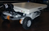
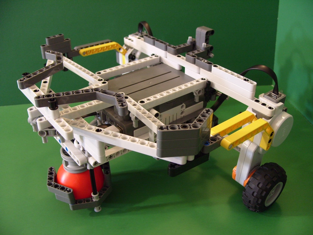
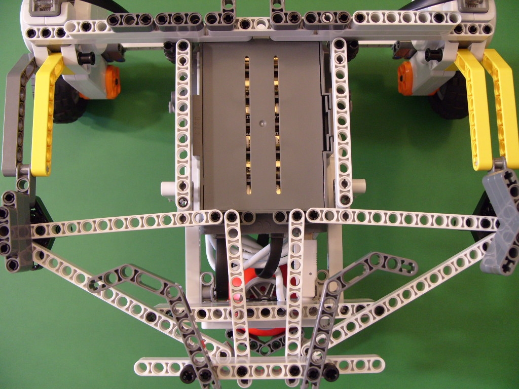
Bot Base
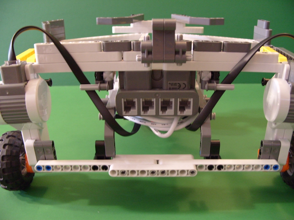
To get an idea of the construction let's have a look at the PC Bot without the laptop or camera attached. Below you can see the scaffholding required in order to support the laptop. Note that the laptop simply drops into the construction and is secure enough for operation but will not be held in if the robot is tilted on its side or carried in any other orientation but upright.

click on image for larger view
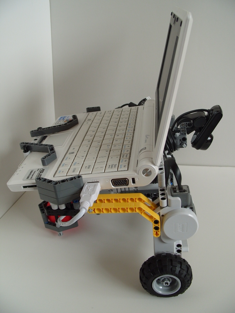
Laptop
The laptop fits snugly into this frame being supported by the web created above the NXT. It is supported in the front with the small wall created between the camera mount and the NXT based. You will also notice the asymetrical size holders (the gray wall connected to the yellow pieces. The asymetry was due to a lack of small straight pieces that were exhaused during the construction of this robot. This was not problematic as the laptop's width is slightly smaller than the span between these two side peices which allowed for one side to use a more curved lego piece. The curved pieces excert more squeezing pressure and allow the laptop to better fit ontop of the base.
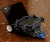
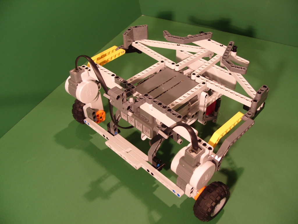
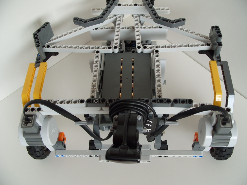
Motors
We chose to position the motors in a vertical manner as apposed to angled as it made the planning easier to work with. It also allowed the NXT brick to be mounted underneath the laptop platform with enough ground clearance to avoid contact.
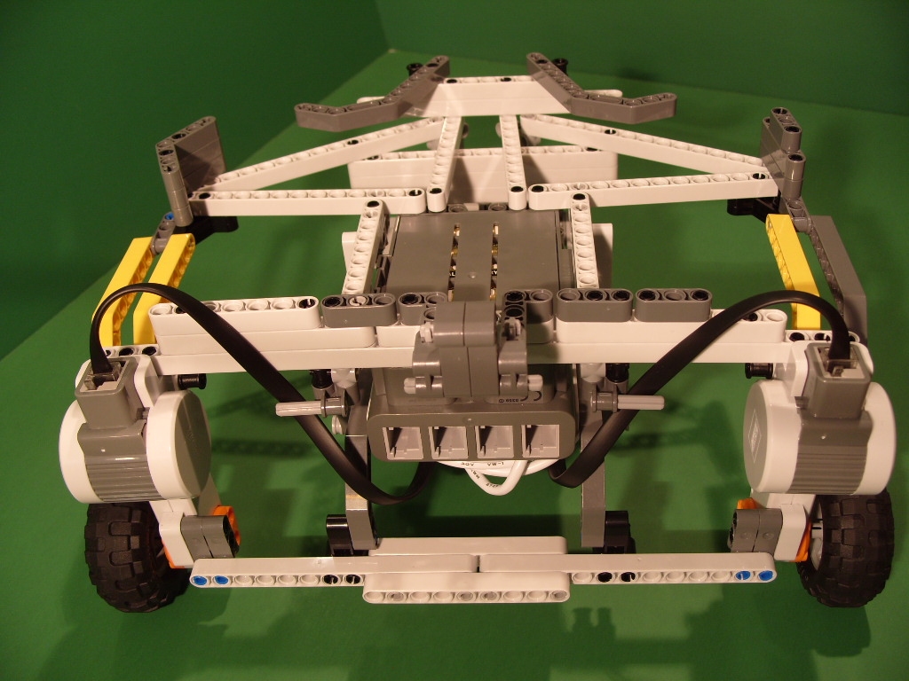
This orientation of the motors, while useful for this specific construction, do add to the instability of the system. When the wheels begin turing they cause the motors to experiance a twisting torque between the wheels and the momentum of the laptop. Thus the robot has a tendency to "fall flat on its face" if the wheels encounter too much resistance.


click on image for larger view
You can notice the excessive connections to the motor in the front view. Note also the curved bar connection between the NXT and the front white span between the motors. This addition helped tremendously to stabilize the robot and prevent the "face falling" that would happen.
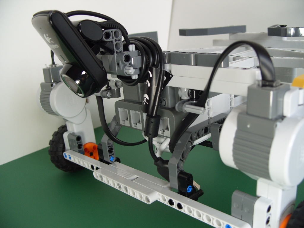
Camera
The logitech camera is built to connect to the top of a laptop. This might imply that a straigh vertical attachment would be all that is necessary to clip the camera onto the robot. However, we found that the better attachment as a small 90 angle which would allow the camera to better clip onto the robot in such a way that it would not move vertically during operation. Note that this required a tricky 90 degree connection to connect a horizontal plan (the laptop base) with a vertically oriented piece.
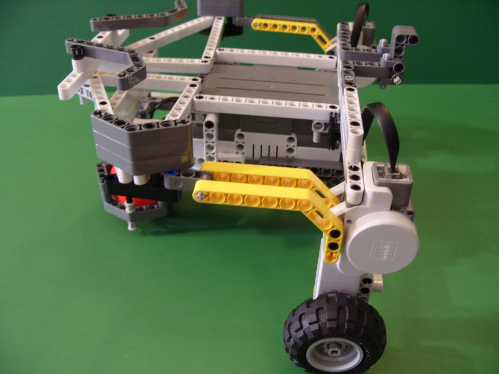
Handles
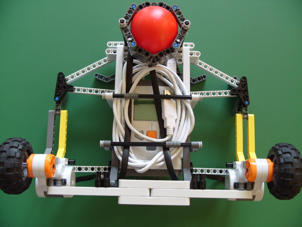
Every robot needs to have a handle which can be used to quickly grab the robot as it zips out of control towards the wall ... or worse off the tabletop! While the we not able to create a design that could be used to carry the robot with one hand we did settle on creating some grasp bars that do allow for easier pickup. You can see these yellow pickup bars connected from the motor to the outmost left and right sides of the laptop platform. These also created more stability in the system by connecting the motor and laptop platform but also serve as grasp handles using two hands to pickup the robot. Prior to these handles the robot would be grasped from the underside using the NXT as a base. This had the unfortunate effect of accidentally turing off or on the NXT base as the orange button on the NXT is slightly raised with respect to the NXT base.
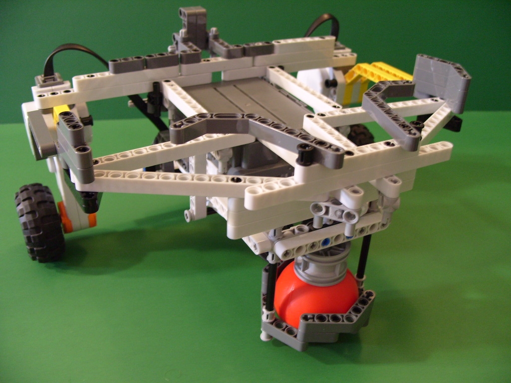
Castor
As you will have already noticed the red ball provided with the Lego NXT kit was used as the laptop castor (or third wheel). We decided not to use the third motor provided in the kit as the rubber wheel would cause too much friction when being forced to the left or right. As the robot is meant for home use the plastic on the ball tends to provide much less friction on a carpet or floor than the third wheel. We also tended away from the other castor implementations seen in other Lego NXT constructions as they are too thin to operate reliably on a thich carpet and tended to cause jerkyness as the robot moved due to the castor wheel slipping into the current orientation.
We also determined that based on the laptop base a lot of weight from the laptop would be resting on the castor which would cause movement issues unless that weight was compensated for by the castor. Thus the red (or blue) ball would work well for distributing the laptop weight and allow the robot to slip over a thick carpet. While the ball mainly slips over the carpet when it does move (over hardwood) it provides a crude omnidirectional wheel.
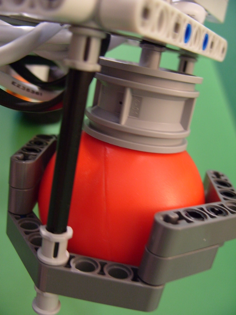
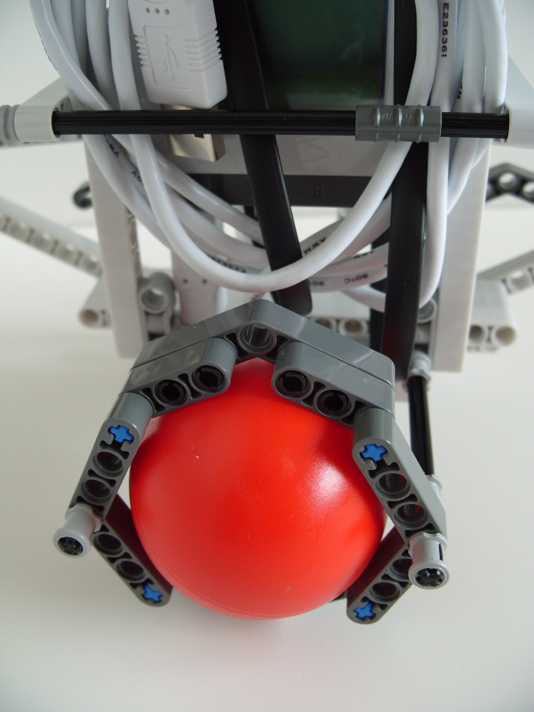

click on image for larger view
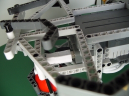
The trick behind the castor is to use the third wheel hub as the main vertical support. This allows the weight of the laptop to be distributed on the wheel and provides a good hold on the ball. The supporting lego pieces seen around the ball are used to hold the ball in position and prevent the ball from simply dropping below the wheel hub holder when in operation or when simply picked up. The left and right black bar supports of that sturcture allow for fine tune adjustment to get the holder into the correct position. With this tuning the ball would either slip out or would require too tight a hold which would prevent the wheel from turing at all.
NXT
The NXT brick is at the center of the construction. It is used to start the web that becomes the laptop base. The NXT is mounted upside down to provide quick access to the on/off buttons that are now accessible from the bottom of the robot. The battery back can still be removed without requiring the robot to be deconstructed and would only require the laptop to be removed in order to change batteries. Normally we run the system with the batteries exposed (i.e. with the battery back) as they are held in place and are easier to switch out without having to remove the battery back (while removable it tends to stick to the sides when being removed).
click on image for larger view
Also note the packing of the USB cable underneath the NXT. We chose not to cut the USB cable down to size as this would require careful reassembly of the cable. You could probably purchase a shorter usb cable to reduce this packing requirement. We chose to use USB as apposed to bluetooth as the NXT connected via a USB cable is much more reliable than using bluetooth especially when in an unknown environment. USB also starts up quicker than the bluetooth connection and offers a audiable beep when the USB becomes connected or disconnected from the NXT.
click on image for larger view
The USB connects to the NXT in the rear just above the castor framework. The other end is connected to one of the 3 USB connections on the Asus Eee.
Camera
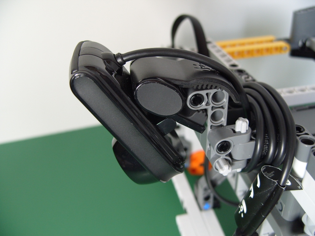
As previously seen the Logitech camera mounts in the front of the robot. Using a 90 degree lego piece the camera gripper attaches quite securely to the front of the robot at an appropirate angle towards the ground.
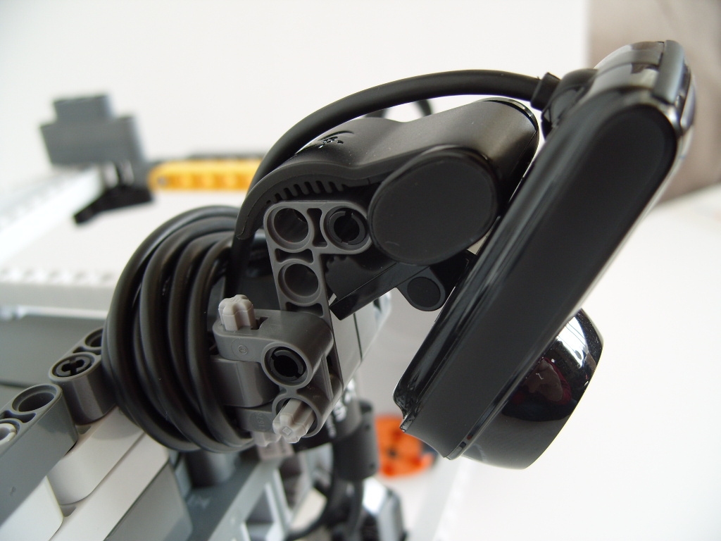

click on image for larger view
Once the camera is clipped onto the holder the wire is simply wrapped around behind the camera to ensure that any tugging on the USB cable will not change the camera orientation. This USB cable is plugged into the side of the Asus Eee and thus is somewhat exposed to obstacles on the side of the robot which might cause some tugging on the wire.
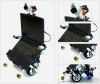
Computer
The Asus is now slipped into the NXT base and the two USB connections (one for the camera and the other for the NXT) are plugged in.


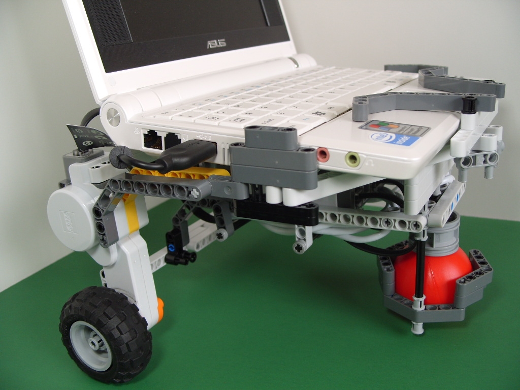
click on image for larger view
Now that the Bot is ready to go we need the software!
Software
We would like to use the Floor Finder obstacle avoidance technique described in the Obstacle Avoidance tutorial to move the robot around the room avoiding obstacles that are not the same color as the floor plane.
We load in the following ![]() robofile which performs
this task specifically using the Lego NXT robot.
robofile which performs
this task specifically using the Lego NXT robot.
Once the video has started and verified we can turn on the NXT. The final task is to press the green Start button in the RoboRealm popup button interface to actually start the robot. This provides a quick way to start and stop the robot and is even possible to click while the robot is moving (tap the mouse pad to click the button).
Videos
Notes:
1. The biggest issue (after Sability of the platform) is the viewable area of the camera. As the camera is pointed towards the ground and the robot base is quite wide the camera cannot see a wide enough view in front of the robot in order to avoid all obstacles. It is possible for an obstacle to slip by the camera view and collide with a wheel. This issue can be solved by either using more than one camera (one for each wheel) or a camera with a wide field of view.
2. There are a couple of issues to solve to make this a reliable platform for continuious use. Improving stability by using a different design or more parts from a second NXT kit would help. In addition the Asus Eee will only last about an hour in terms of power. As the system does not have a charging solution continious operation is not possible at this point. Note that there are two power systems in operation with this platform, the laptop being one and the other being the NXT.
3. Note that none of the other sensors available in the Lego NXT are NOT being used. One could improve the reliability of this implemention by adding in the other sensors. The sensor attachment side of the NXT is kept clear to allow for these additions. Again, all these sensors could work in conjuction with the onboard vision system either within the NXT or combined with the vision logic within RoboRealm.
The End
That's all folks. We hope you've enjoyed this little adventure into an application of machine vision processing. If you have any questions or comments about this tutorial please feel free to contact us.
Have a nice day!
| New Post |
| Lego PC Bot Related Forum Posts | Last post | Posts | Views |
| None |