
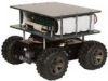
CoroWare CoroBot
The CoroWare CoroBot module provides an interface to the CoroBot robot created by CoroWare and distributed by RoadNarrows. The CoroBot is a PC based robot that is capable of running RoboRealm onboard (WinXP version). The robot is constructed using several standard interface cards that allow the PC to communicate to the underlying hardware using both serial and USB connections. The CoroBot uses the Lynxmotion SSC for motor and arm control, the Phidgets Encoder board for motor encoders and the Phidgets 888 Interface Kit to read the battery voltage, gripper switch and front/back IR distance sensors.While the CoroBot module provides connection to all the required boards to command the robot you can also disable the appropriate segments and instead add in the full board modules supported by RoboRealm if you need lower level interfacing or require more aspects of that particular board. For example, if you need to add additional IR sensors you can disable the Sensor group in this interface and add in the Phidgets 888 Interface Kit board to provide you with the current 4 sensors (Battery, Front/Back IR, Gripper Touch) and any additional channels you may need.
The CoroBot contains a full PC, therefore all other modules within RoboRealm such as the Play Wave File and Speech Recognition will work with the appropriate attachment of speakers, mic, etc.
Interface
Instructions
1. Motors - Select the checkbox next to "Motors" to enable the motor channels. To test the motors slowly move the appropriate sliders. If everything is working the motors should slowly start to move. If this does not happen check that your SSC is connected and configured on COM2.
If the motors move you can then select a variable (or type one in) that will be populated from another module that will contain the values to send to the CoroBot. 1500 is considered neutral whilst 1000 and 2000 are the opposite backward/forward extremes.
When a variable is selected the slider and value controls will be disabled to indicate that control is now performed through the use of a variable.
You can change the Min and Max values for the motors. This will ensure that regardless of the variable's value that the motors will never be sent a command beyond those limits. You can tighten the limits to 1250 and 1750 to ensure that the robot moves slowly regardless of variable errors.
Keep in mind that the CoroBot runs both wheels on either side at the same speed. So to pivot set one side to a value higher than 1500 and the other side to less than 1500. Speeds while moving forward versus turning will differ due to the stress placed on the wheels when turning. Also keep in mind that the CoroBot runs better over floors than carpet largely due to the wheel friction during turning on carpet.
The Motor commands are passed to the Lynxmotion SSC to perform the actual servo movements.
See Variable Control for more information on how to programatically move the robot.
2. Enable PID - Enables Proportional, Integral, Derivative control over motor movements. This formula will adjust the actual motor values to be different than that of the desired motor values to ensure that the motors are actually moving in such a way that best represents the desired speed. For example, if you are traveling along a flat surface with motor speeds set at 1300 (slowly forward) and suddenly encounter a hill this slow speed will not suffice to get the robot over the hill. With the PID loop enabled the lack of actual motion will be sensed by the reduced encoder count and cause the actual motor values to increase such that the encoders continue to report the same count. Thus the robot will not slow down when encountering a hill. See Wikipedia for more information about PID loops.
3. Arm - Select the checkbox next to "Arm" to enable the optional Lynxmotion Arm controls. Please note that as the arm moves beyond its actual abilities increasing X or Y may cause the arm to move in unexpected ways. Also note that it is possible to position the arm in a destructive position such as against the robot or below the floor. The following controls are very unrestricted and limits should be reduced depending on your application to prevent the arm from damage.
The Arm commands are passed to the Lynxmotion SSC to perform the actual servo movements.
4. Arm X - Select or type in a variable that will contain the desired X location of the arm. X is always positive and moves the arm horizontally parallel to the floor plane. The numbers specified are in millimeters. Modifying the X location will change the Shoulder and Elbow angles accordingly (inverse kinematics).
5. Arm Y - Select or type in a variable that will contain the desired Y location of the arm. Y can be negative (touching the floor) and moves the arm vertically. The numbers specified are in millimeters. Modifying the X location will change the Shoulder and Elbow angles accordingly (inverse kinematics).
6. Arm Wrist - Select or type in a variable that will contain the desired wrist degree that ranges from -90 to 90 with 0 being horizontal.
7. Arm Gripper - Select or type in a variable that will contain the desired width of the gripper that ranges from 0 (Open) to 254 (Closed).
8. Arm Shoulder - Select or type in a variable that will contain the desired shoulder degree of the arm. Changing this value will change the X and Y location of the arm accordingly (forward kinematics).
9. Arm Elbow - Select or type in a variable that will contain the desired elbow degree of the arm. Changing this value will change the X and Y location of the arm accordingly (forward kinematics).
10. Arm Speed - Select how quickly that the arm will move. Higher millisecond times will case the arm to move slower. Smaller times will cause the arm to move faster but become much more jerky when moving due to servo torques.
11. Sensors - Check the checkbox to enable sensor readings. The Sensors use the Phidgets 888 Interface Kit to read the appropriate values.
12. Front Sensor - Select or type in a variable that will contain the IR sensor reading in the front of the robot. This sensor will typically range from around 0 to 500 with 500 being very close. Once objects pass nearer than the 500 mark the values may actually decrease slightly before the object contacts with the robot.
13. Back Sensor - Select or type in a variable that will contain the IR sensor reading in the back of the robot. This sensor will typically range from around 0 to 500 with 500 being very close. Once objects pass nearer than the 500 mark the values may actually decrease slightly before the object contacts with the robot.
14. Battery Sensor - Select or type in a variable that will contain the battery voltage. The voltage will range from a peak of 12 volts down to zero (note that the robot will stop functioning well before 0 is reached!).
15. Gripper Sensor - Select or type in a variable that will contain the pressure value of the touch sensor within the gripper. A value of 1000 means the gripper is very securely closed with a value of 0 meaning nothing is touching.
16. Encoders Left/Right - Select or type in a variable that will contain the left and right encoder values read from the motor encoders. These values are also used internally by the PID loop to ensure constant motor movement.
17. Rotate Image - Often the CoroBot camera is mounted upside down. Select this checkbox to flip the image over for easier viewing.
Examples
It is HIGHLY recommended to place the CoroBot on a stand before accessing any of the below examples. Some tests will require the joystick #1 button to be pressed in order to start but others will not. Thus accessing any of the following examples and running them on the CoroBot may suddenly cause the robot to start moving in a possibly hazardous direction.
Due to the high friction of the CoroBot wheels most of these demos will NOT work correctly on thick carpet as the robot is unable (even with PID enabled) to pivot in place. Try it with the Joystick demo to see if your carpet passes the test!
Joystick
![]() Click Here to load a robofile that will allow you to drive your CoroBot using a joystick. When you load this configuration
you will need to edit the Joystick module to select which joystick to use to control the robot.
Click Here to load a robofile that will allow you to drive your CoroBot using a joystick. When you load this configuration
you will need to edit the Joystick module to select which joystick to use to control the robot.
This robofile is configured for a playstation type of joystick with the first knob providing motion control. Moving the knob forward/backward moves the robot forward/backward. Moving the knob left/right pivots the robot in the appropriate direction (if not on carpet!). Moving the second knob forward/backwards moves the arm up/down (Y axis) and moving left/right moves the arm forward/backward (X axis). Clicking buttons 6 and 8 opens and closes the gripper with buttons 5 and 7 twisting the arm.
If you do not like the configuration we have chosen simply edit the Joystick module and change the variables around to different buttons.
Once that is done have a safe and happy drive!
Laser Steering
![]() Click Here to load a robofile that will allow you to drive your CoroBot using a red laser light spot placed in front of the
robot visible from the camera. You should adjust the camera to a higher location than
installed by default and angled down towards the floor in order for this example to work. The higher location of the camera will allow
more coverage in front of the robot. The default camera has a narrow field of view and cannot see much floor space
in front of the robot as installed.
Click Here to load a robofile that will allow you to drive your CoroBot using a red laser light spot placed in front of the
robot visible from the camera. You should adjust the camera to a higher location than
installed by default and angled down towards the floor in order for this example to work. The higher location of the camera will allow
more coverage in front of the robot. The default camera has a narrow field of view and cannot see much floor space
in front of the robot as installed.
By moving the laser forward the robot will move forward, placing the laser spot close to the robot will cause it to back up. Moving it to the side will cause the robot to pivot. Be sure not to move the laser too quickly and keep it within view of the camera.
Be warned that any spot lights maybe detected as laser lights and cause the robot to move at random. Be sure to test on blocks before releasing the robot.
IR Avoidance
![]() Click Here to load a robofile that will cause the CoroBot to avoid objects using the forward IR sensor. The strategy is
to run forward until a close object is detected, back up for a few encoder counts, rotate and then
proceed forward. Be sure to test this while the robot is elevated before committing the robot to moving
towards a wall!
Click Here to load a robofile that will cause the CoroBot to avoid objects using the forward IR sensor. The strategy is
to run forward until a close object is detected, back up for a few encoder counts, rotate and then
proceed forward. Be sure to test this while the robot is elevated before committing the robot to moving
towards a wall!
Laser Line Avoidance
![]() Click Here to load a robofile that will cause the CoroBot to avoid objects using a red laser line
as seen in the Laser line module. The CoroBot does NOT come with
a laser line and thus you will have to purchase one in order to use this example.
Click Here to load a robofile that will cause the CoroBot to avoid objects using a red laser line
as seen in the Laser line module. The CoroBot does NOT come with
a laser line and thus you will have to purchase one in order to use this example.
Using the red laser line (ideally in a low light situation) the robot can detect objects and turn to avoid them with more reliability than using the IR detector. The additional reliability is due to the larger field of view that is possible with the camera + laser line than what the IR detector will provide.
You should adjust the camera to a higher location than installed by default and angled down towards the floor.
Keep pressing the Joystick button #1 in order for this demo to run. Releasing the button will cause the CoroBot to stop.
Line Following
![]() Click Here to load a robofile that will cause the CoroBot to follow a line using the build in camera.
You should adjust the camera to a higher location than
installed by default and angled down towards the floor in order for this example to work.
The line is ideally black electrical tape against a white floor. If you instead have a white line
on a black floor disable or delete the Negative module in this example.
Click Here to load a robofile that will cause the CoroBot to follow a line using the build in camera.
You should adjust the camera to a higher location than
installed by default and angled down towards the floor in order for this example to work.
The line is ideally black electrical tape against a white floor. If you instead have a white line
on a black floor disable or delete the Negative module in this example.
Keep pressing the Joystick button #1 in order for this demo to run. Releasing the button will cause the CoroBot to stop.
See Also
Lynxmotion SSC
Phidgets 888 Interface Kit
Phidgets Encoder
Rotate
For more information
RoadNarrows
| New Post |
| CoroWare_CoroBot Related Forum Posts | Last post | Posts | Views |
|
Coroware Corobot module variables
I was wondering if you can give me more detail about how the arm_x and arm_y values are calculated based on shoulder and elbow v... |
11 year | 3 | 2393 |